Sponge slicing method and sponge slicing fixing device for automobile cushion

A technology for car seat cushions and fixing devices, which is applied in metal processing and other directions, can solve problems such as large errors, complex structures, and inability to be fixed by sponges, and achieve the effect of reducing friction

Active Publication Date: 2017-07-25
南通斯麦汽车内饰材料有限公司
6 Cites 1 Cited by

AI-Extracted Technical Summary

Problems solved by technology

Not only the structure is complicated, but also the sponge t...

Method used

Wherein, also be provided with collection mechanism 3, collection mechanism 3 is provided with aspirator 301, aspirator 301 connects aspirator 302, and aspirator 301 end is provided with inward ...

Abstract

The invention discloses a sponge slicing method for an automobile cushion. The sponge slicing method comprises a longitudinal cutting step and a transversal cutting step, wherein during longitudinal cutting, sponge is longitudinally flattened, and then the longitudinal cutting is carried out on the sponge in the flattened state by virtue of a cutting device; and during transversal cutting, the sponge is inflated by virtue of an inflator, and the transversal cutting is carried out on the sponge by virtue of a cutting device. According to the sponge slicing method disclosed by the invention, during the longitudinal cutting, a piston is pressed by a hydraulic cylinder to flatten the sponge to be cut in a compression barrel, and then the cutting is carried out, so that the displacement and the deformation of the sponge generated during the cutting process can be avoided; during the transversal cutting, a rubber film is arranged on the sponge to be cut in a sleeving manner by virtue of an elastic band, a connection valve is opened, the inflator inflates the sponge, at this moment, the sponge has a certain hardness due to inflation inside and cannot generate large-amplitude deformation during the cutting, and a fixing plate is extruded by a spring to be abutted against the sponge to further realizing fixing; and the two manners improve the cutting accuracy of the sponge.

Application Domain

Metal working apparatus

Technology Topic

PistonCushion +4

Image

  • Sponge slicing method and sponge slicing fixing device for automobile cushion
  • Sponge slicing method and sponge slicing fixing device for automobile cushion
  • Sponge slicing method and sponge slicing fixing device for automobile cushion

Examples

  • Experimental program(1)

Example Embodiment

[0022] The technical solutions in the embodiments of the present invention will be clearly and completely described below in conjunction with the accompanying drawings in the embodiments of the present invention. Obviously, the described embodiments are only a part of the embodiments of the present invention, rather than all the embodiments. Based on the embodiments of the present invention, all other embodiments obtained by those of ordinary skill in the art without creative work shall fall within the protection scope of the present invention.
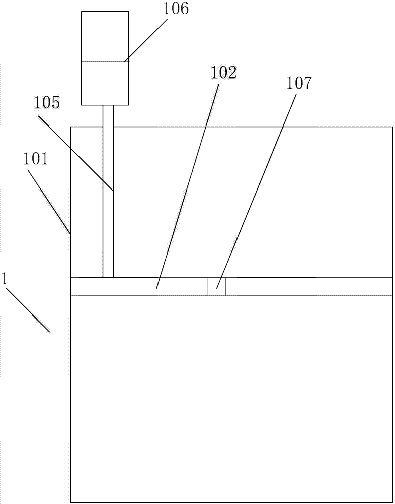
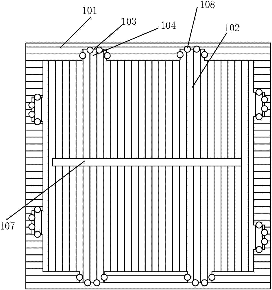
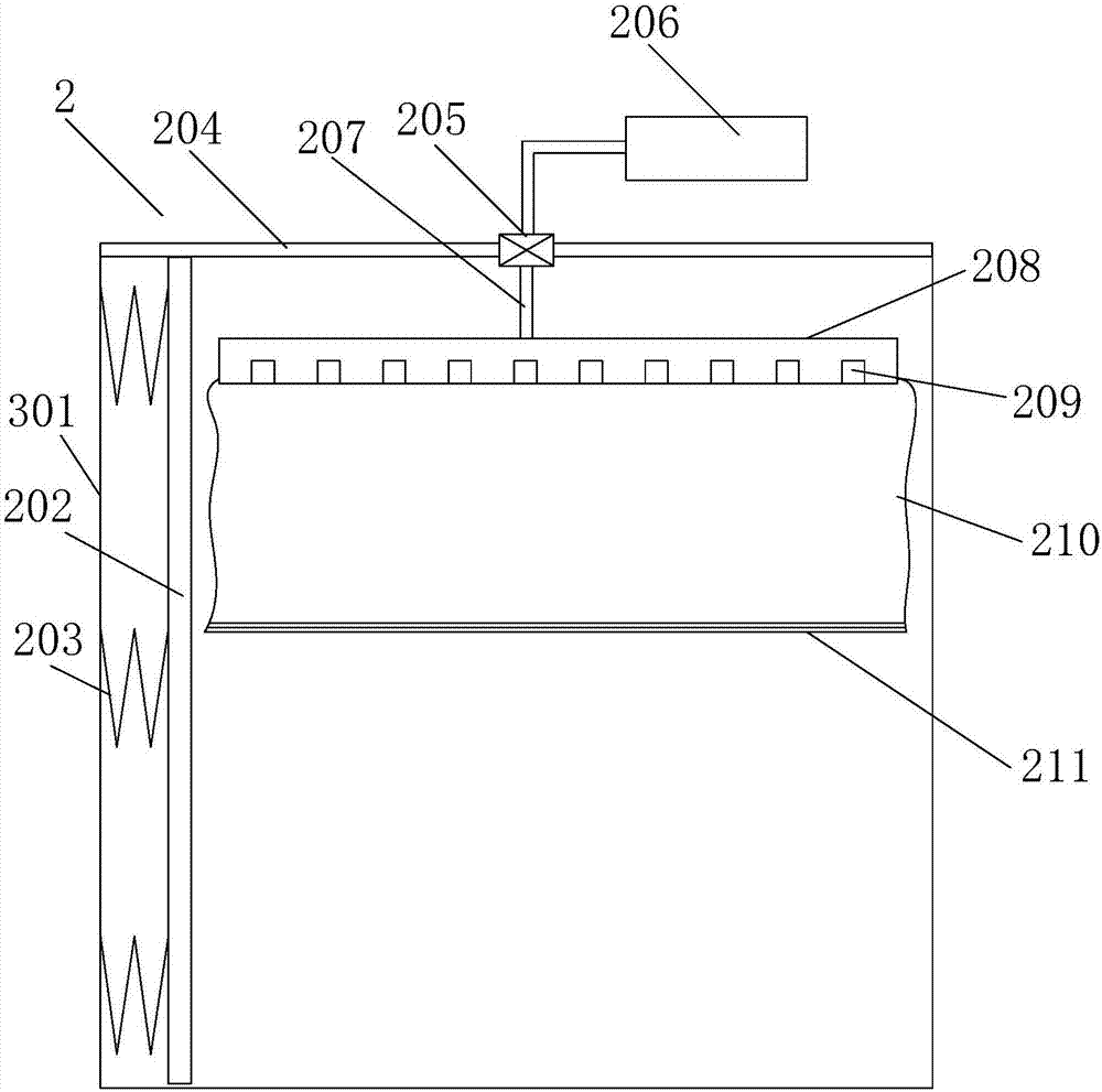
[0023] Such as Figure 1-4 As shown, the present invention is a sponge cutting method for car seat cushions, which includes a longitudinal cutting step and a transverse cutting step; when the longitudinal cutting is performed, the sponge is longitudinally flattened, and then the cutting device is used to longitudinally cut the flat sponge ; When performing transverse cutting, use an inflator to inflate the sponge. When the sponge is in a fully expanded state, use a cutting device to cut the sponge transversely.
[0024] Among them, it also includes a collection step, using a collecting device to collect the scraps generated during the cutting process to prevent the scraps from rising up and interfering with the normal operation of the equipment.
[0025] A sponge cutting and fixing device for automobile seat cushions includes a longitudinal cutting fixing mechanism 1 and a transverse cutting fixing mechanism 2; the longitudinal cutting fixing mechanism 1 is provided with a compression cylinder 101, the compression cylinder 101 is provided with a piston 102, and the inner wall of the compression cylinder 101 is also provided There is a sliding groove 103, the piston 102 is circumferentially provided with a sliding block 104 matching the sliding groove 103, the top of the piston 102 abuts the vertical rod 105, the top of the vertical rod 105 is connected to the hydraulic cylinder 106, and the middle of the piston 102 is provided with a strip through hole 107; The cutting and fixing mechanism 2 is provided with an inflator 201. The inflator 201 is provided with a longitudinally arranged fixed plate 202. The fixed plate 202 is connected to the inner wall of the inflator 201 through a spring 203. The top of the inflator 201 is provided with a cylinder cover 204, and the top of the cylinder cover 204 A connecting valve 205 is provided. The two ends of the connecting valve 205 are respectively connected to the inflator 306 and the tube 207. The end of the tube 207 is provided with an inflatable disk 208, the inflatable disk 208 is provided with air holes 209, and the inflatable disk 208 is also provided with a skirt rubber membrane 210. The top of the membrane 210 is sleeved at the end of the inflatable disk 208, and the end of the rubber membrane 210 is provided with a circumferentially distributed elastic band 211.
[0026] Wherein, a ball 108 is provided between the sliding groove 103 and the sliding block 104. When the sliding block 104 slides in the sliding groove 103, the rolling ball 108 can effectively reduce friction.
[0027] Among them, there is also a collection mechanism 3, the collection mechanism 3 is provided with a suction tube 301, which is connected to the air extractor 302, the end of the suction tube 301 is provided with an inward cone-shaped cover 303, and the middle of the cone-shaped cover 303 is provided The vent 304 prevents the debris generated in the cutting process from interfering with the stable operation of the equipment.
[0028] Among them, the air inlet of the air extractor 302 is provided with a filter 305 to prevent debris from entering the air extractor 302 to damage the equipment.
[0029] A specific application of this embodiment is: during longitudinal cutting, the hydraulic cylinder 106 presses against the piston 102 to flatten the sponge to be cut in the compression cylinder 101, and then cuts. When the piston 102 moves up and down in the compression cylinder 101, The sliding block 104 is displaced in the sliding groove 103 to ensure that the piston 102 remains level, which can avoid the displacement and deformation of the sponge during the cutting process; when cutting transversely, use the elastic band 211 to cover the rubber film 210 on the sponge to be cut. Open the connection valve 205, and the inflator 206 inflates the sponge. At this time, the sponge has a certain degree of hardness due to the inflation inside the sponge, and there will be no significant deformation during cutting. At the same time, the spring 203 squeezes the fixed plate 202 against the sponge. , To further realize the fixation; the above two methods improve the cutting accuracy of the sponge.
[0030] In the description of this specification, the description with reference to the terms "one embodiment", "example", "specific example", etc. means that the specific features, structures, and materials described in conjunction with the embodiment or example are included in the present invention. In at least one embodiment or example. In this specification, the schematic representations of the above terms do not necessarily refer to the same embodiment or example. Moreover, the described specific features, structures, materials or characteristics may be combined in any one or more embodiments or examples in a suitable manner.
[0031] The preferred embodiments of the present invention disclosed above are only used to help explain the present invention. The preferred embodiment does not describe all the details in detail, nor does it limit the invention to only the described specific embodiments. Obviously, many modifications and changes can be made according to the content of this manual. This specification selects and specifically describes these embodiments in order to better explain the principles and practical applications of the present invention, so that those skilled in the art can understand and use the present invention well. The present invention is only limited by the claims and their full scope and equivalents.

PUM

no PUM

Description & Claims & Application Information

We can also present the details of the Description, Claims and Application information to help users get a comprehensive understanding of the technical details of the patent, such as background art, summary of invention, brief description of drawings, description of embodiments, and other original content. On the other hand, users can also determine the specific scope of protection of the technology through the list of claims; as well as understand the changes in the life cycle of the technology with the presentation of the patent timeline. Login to view more.

Similar technology patents

Masking plate and array substrate manufacturing method

InactiveCN107275522Areduce frictionreduce scratches
Owner:SHANGHAI TIANMA AM OLED

Easy-to-demould precoated sand and production process of easy-to-demould precoated sand

InactiveCN102672109Areduce frictionImprove yield and pass rate
Owner:广东省铸力铸材科技有限公司

Classification and recommendation of technical efficacy words

  • reduce friction

Hand force feedback and sensing system

InactiveUS7138976B1reduce friction
Owner:RUTGERS UNIVERSITY

Electrical connector with voltage detection point insulation shield

ActiveUS6843685B1reduce frictionreduces wear and clean
Owner:THOMAS & BETTS INT INC

One piece low drag septum

ActiveUS20070093778A1reduce friction
Owner:BECTON DICKINSON & CO

Combination oil ring

InactiveUS20060113730A1reduce frictionenhanced capability
Owner:TOYOTA JIDOSHA KK +1

Apparatus for deploying endoscope

InactiveUS20100198012A1reduce frictionless effective
Owner:SCOPEGUARD LTD
Why Eureka
Try Eureka