
Turnover production line for articles large in surface friction coefficient difference

A technology with surface friction and large differences, applied to impact-sensitive items, types of packaging items, conveyor items, etc., can solve the problems of error-prone, high cost, small ceramic identification features, etc., and achieve high reliability of flipping , the effect of high turning efficiency

Inactive Publication Date: 2017-07-25
佛山市埃科机器人科技有限公司
View PDF16 Cites 1 Cited by
  • Summary
  • Abstract
  • Description
  • Claims
  • Application Information

AI Technical Summary

Problems solved by technology

[0002] Articles such as ceramics and block glass products are sold in the form of plates, so they need to be plated during packaging. Taking ceramics as an example, in the past, ceramics were plated manually, which was low in efficiency and high in cost. Error prone to rework
Nowadays, mechanical arrangement is gradually adopted. When using mechanical arrangement, it is necessary to unify the front and back of ceramics. The commonly used methods in the market are: 1. Use the vibrating plate to feed materials to identify the front and back of ceramics. The disadvantage is that most ceramics are due to identification characteristics. It is too small to be discriminated at all, and at the same time, it is noisy, and there is a risk of damage to ceramics; 2. Using photoelectric detection, its disadvantage is that although it can quickly detect the front and back sides, it also needs an external flip mechanism, which is inefficient; 3. Vision The disadvantage of lens inspection is that it is costly. After detecting the front and back sides, it needs to take out the turning mechanism, which is inefficient.

Method used


Image

  • Turnover production line for articles large in surface friction coefficient difference
  • Turnover production line for articles large in surface friction coefficient difference
  • Turnover production line for articles large in surface friction coefficient difference

Examples


Embodiment Construction

[0016] The present invention will be further described below in conjunction with specific embodiments:

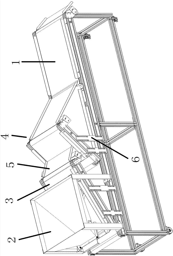
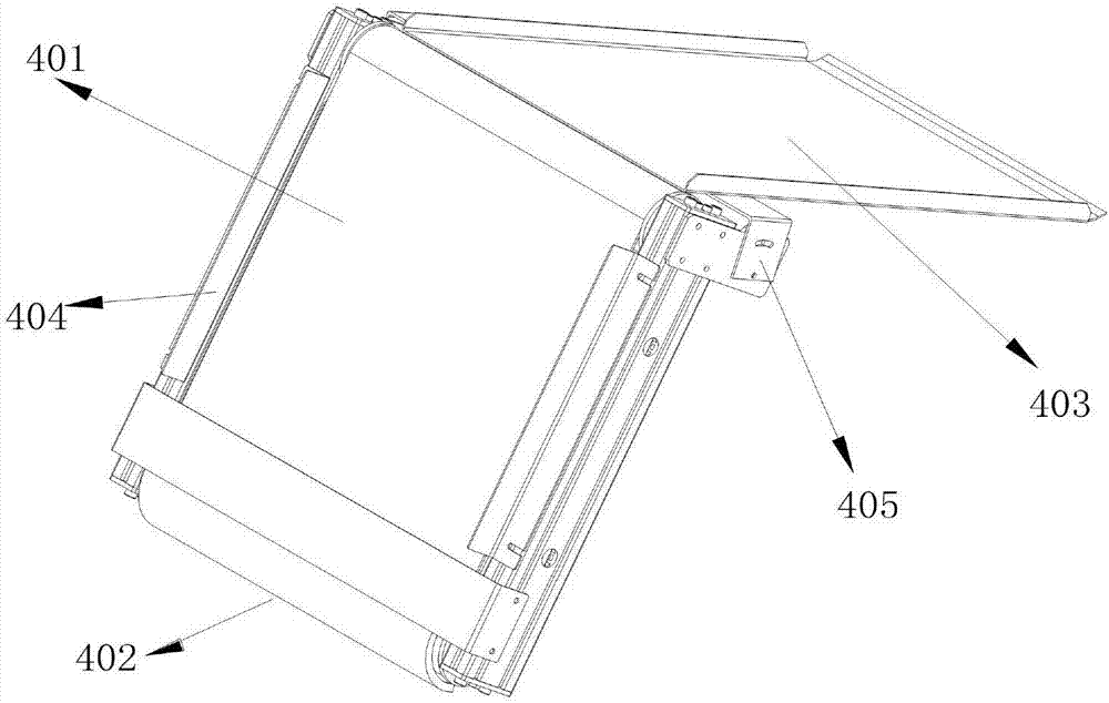
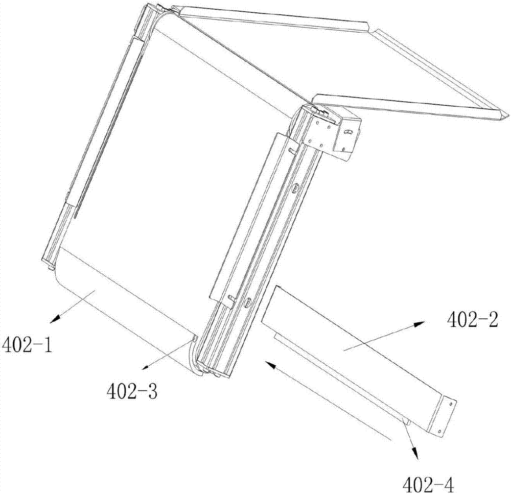
[0017] See attached Figure 1 to 3 As shown, the reversing line for items with large differences in surface friction coefficients in this embodiment includes a discharge conveyor line 1, a storage hopper 2, a shunt conveyor line 3, and a reversing device 4. The items have two different surface friction coefficients. Larger ceramics. Among them, the storage hopper 2 and the turning device 4 are successively erected in the downstream direction above the discharge conveying line 1. The branching conveying line 3 is located between the storage hopper 2 and the turning device 4, and the branch is conveyed There is a transition slide 5 for transition between the line 3 and the transmission conveying mechanism 401, which transports the ceramics from the storage hopper 2 to the turning device 4; the turning device 4 is transmitted by a transmission and conveying mechanism 401 using a ...


PUM


Abstract

The invention relates to a turnover production line for articles large in the surface friction coefficient difference. The turnover production line comprises a discharged material conveying line, a storage hopper, a dividing conveying line and a turnover device; the storage hopper and the turnover device are sequentially arranged over the discharged material conveying line towards the downstream portion; the dividing conveying line is located between the storage hopper and the turnover device; and the turnover device is composed of a transmission conveying mechanism and a rotary positioning mechanism, the rotary positioning mechanism is installed at one end of the transmission conveying mechanism, a sliding conveying mechanism is connected to the end, away from the rotary positioning mechanism, of the transmission conveying mechanism, and an angle adjusting mechanism is arranged at the joint of transmission conveying mechanism and the sliding conveying mechanism. Through the turnover production line, whether the articles need to be turned over or nor is judged according to the fact that the front face and the back face of each article are different in friction coefficient, the articles are not damaged at all during turning over, and the turnover efficiency of the turnover production line is 1000 times or more that of turnover equipment on the market; and the turnover reliability is high, the accuracy rate is 99.5% of above, noise is avoided during turning over, and the surrounding work environment is not influenced at all.

Description

Technical field [0001] The present invention relates to the technical field of production of articles with large differences in surface friction coefficients, and in particular to a turning line for articles with large differences in surface friction coefficients. Background technique [0002] Ceramics and bulk glass products are all sold in the form of plates, so they need to be arranged in the packaging. Take ceramics as an example. In the past, ceramic plates were arranged manually, which is inefficient and costly. Error-prone and need to be reworked. Nowadays, mechanical arranging plates are gradually adopted. When mechanical arranging plates are used, the front and back sides of ceramics need to be unified. At present, the commonly used methods on the market are: 1. Use the vibrating plate to feed the ceramic front and back sides. The disadvantage is that most of the ceramics are due to the identification characteristics Small is still impossible to distinguish. At the same...

Claims


Application Information

Patent Timeline
Patent Type & Authority Applications(China)
IPC IPC(8): B65G47/248B65G49/06B65B35/56B65B23/20
CPCB65B23/20B65B35/56B65G47/248B65G49/067
Inventor 刘旭涌
Owner 佛山市埃科机器人科技有限公司
Learn More