Mechanical transmission mechanism with overload position capable of being preset

A technology of mechanical transmission and transmission shaft, which is applied to mechanical equipment, transmission devices, gear transmission devices, etc., and can solve the problem that the overload position cannot be preset.

Pending Publication Date: 2017-07-25
陈王颖
View PDF1 Cites 4 Cited by
  • Summary
  • Abstract
  • Description
  • Claims
  • Application Information

AI Technical Summary

Problems solved by technology

[0003] The invention provides a mechanical transmission mechanism that can preset the overload position, whi...

Method used


Image

  • Mechanical transmission mechanism with overload position capable of being preset
  • Mechanical transmission mechanism with overload position capable of being preset
  • Mechanical transmission mechanism with overload position capable of being preset

Examples


Embodiment 2

[0028] Embodiment two, the difference with embodiment one is:

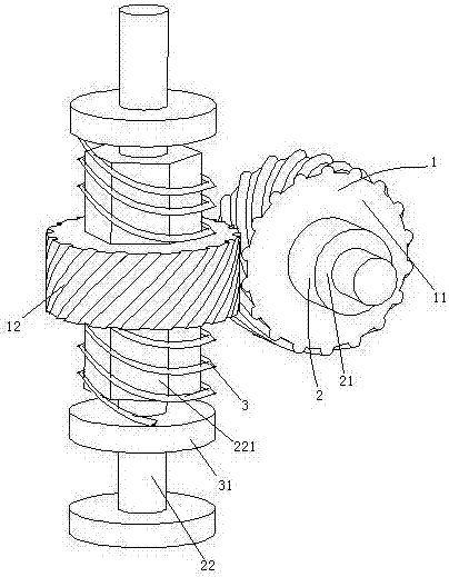
[0029] see figure 2 , when an overload occurs, the driving gear 11 and the driven gear 12 are still meshed together.

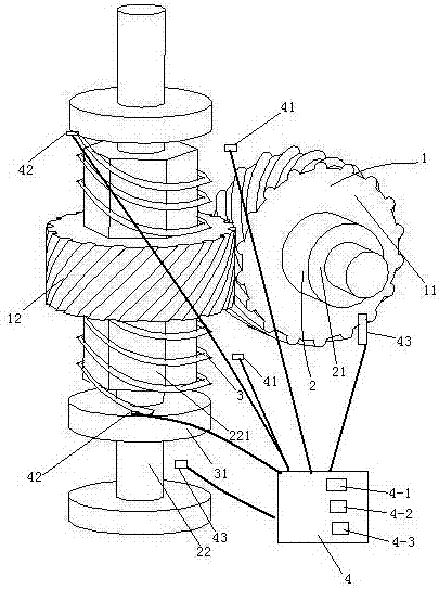
[0030] It also includes a control device 4 , an overload detection switch 41 , a pressure sensor 42 and an angle detection sensor 43 that are electrically connected together. The control device 4 includes a first control unit 4-1, a second control unit 4-2 and a third control unit 4-3.

[0031] There are two overload detection switches 41, which are respectively used to detect when the driven gear 12 forwardly rotates to the overload position and reversely rotates to the overload position and feeds back to the control device.

[0032] The first control unit 4 - 1 stops the power source providing power to the driving gear 11 from outputting power to the driving gear 11 when the first control unit 4 - 1 detects that the driven gear 12 is in the overload position.

[0033] There are two pressure ...

Embodiment 3

[0038] Embodiment three, the difference with embodiment two is:

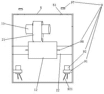
[0039] see image 3 , also includes the gear box case 5 and the overload discriminating structure 9. The driving gear 11 and the driven gear 12 are connected in the gearbox housing 5 through the rotating shaft 21 and the driven shaft 22 respectively. The gear box case 5 is provided with two light-transmitting holes 51 .

[0040] There are two overload judging structures 9 . Since the overload position can be set for both directions of rotation, two overload detection structures 9 are required. If the overload bit setting is only performed in one direction of rotation, only one overload judging structure 9 is required.

[0041] The overload judging structure 9 includes a projection board 97 , a light blocking board 98 and a laser diode 92 . The laser diode 92 is provided with a power input pin 921 . The laser diode 92 is fixed on the heat sink 91 . The projection plate 97 is located on the outside of the g...

Embodiment 4

[0047] Embodiment four, the difference with embodiment three is:

[0048] see Figure 5 , one end of the heat conducting sleeve 934 and one end of the heat sink 91 are sealed against the sealing plate 94 , that is, both the heat conducting sleeve and the heat sink can slide relative to the sealing plate 94 . The other end of the heat conducting sleeve 934 and the other end of the radiator 91 are sealed and connected together through the annular liquid storage bag 95 . The annular liquid storage bag 95 is filled with heat-insulating liquid, and the heat-insulating liquid makes the annular liquid storage bag 95 in an elastically expanded state. When the temperature is below 25° C., a sealed cavity 96 is formed among the heat conducting sleeve 934 , the sealing plate 94 , the radiator 91 and the annular liquid storage bag 95 . The sealed cavity 96 communicates with the annular liquid storage bag 95 .

[0049] When in use, when it is lower than 25°C, the cold shrinkage will cau...


PUM


Abstract

The invention relates to a mechanical transmission mechanism. A mechanical transmission mechanism that can preset an overload position, comprising a pair of meshed gears and an overload position setting spring, the gears are helical gears, and at least one gear in the pair of gears is slidable in the axial direction Sleeved on the transmission shaft and at least one end is supported by the overload position setting spring, when the pair of gears rotate, the gears slidably sleeved on the transmission shaft generate axial movement to drive the overload position setting spring Deformation energy storage, when the load driven by the mechanical transmission mechanism reaches the set upper limit, the position of the gear slidably sleeved on the transmission shaft is the overload position. The invention provides a mechanical transmission mechanism whose overload position can be preset, which solves the problem that the overload position of the existing mechanical transmission mechanism cannot be preset.

Description

technical field [0001] The invention relates to a mechanical transmission mechanism, in particular to a mechanical transmission mechanism with a preset overload position. Background technique [0002] In order to prevent damage caused by overload during mechanical transmission, a guarantee device is often installed for protection. For example, the patent No. 201420566905.5 uses balls as the coaxial overload protection structure. The existing mechanical transmission mechanism can only set the magnitude of the overload force, and realize overload protection by mechanical means (such as friction caused by slipping, component breakage), and cannot set the position of the gear of the transmission mechanism when overloaded (that is, overload bit), thus making it difficult to implement overload protection through electrified means. Contents of the invention [0003] The invention provides a mechanical transmission mechanism whose overload position can be preset, which solves th...

Claims


Application Information

Patent Timeline
IPC IPC(8): F16H35/10F16H1/18F16H57/01H01S3/04
CPCF16H35/10F16H1/18F16H57/01F16H2035/106F16H2057/012F16H2057/016H01S3/0405
Inventor 陈王颖
Owner 陈王颖
Why Eureka
Try Eureka