Device for detecting air impermeability of component and detecting method thereof

A technology of air tightness detection and parts, which is applied in the direction of liquid tightness measurement using liquid/vacuum degree, by measuring the increase and deceleration rate of fluid, and assisting non-electric fluid pressure control, etc., which can solve the problem of insufficient protection of parts installation and the result Inadequate precision, insufficient installation sealing, etc., to achieve the effect of convenient test installation, accurate measurement results, and guaranteed sealing

Inactive Publication Date: 2017-07-25
刘丽华
View PDF0 Cites 3 Cited by
  • Summary
  • Abstract
  • Description
  • Claims
  • Application Information

AI Technical Summary

Problems solved by technology

[0002] ​The air tightness test of parts is often encountered in industrial production. At present, the air tightness test of parts is mostly manual visual inspection method, that is, put the part into the liquid to inflate, and then observe whether the outer surface of the part is There are air bubbles leaking; in addition, there are some special mechanical testing equipment, but they are not perfect and mature. The main aspects are that the testing results are not accurate enough, the installation sealing is not enough, and the parts installation protection is not enough, which leads to inaccurate measurement results. Accurate, and the workpiece is damaged during the measurement process, etc.

Method used


Image

  • Device for detecting air impermeability of component and detecting method thereof
  • Device for detecting air impermeability of component and detecting method thereof
  • Device for detecting air impermeability of component and detecting method thereof

Examples


Embodiment 1

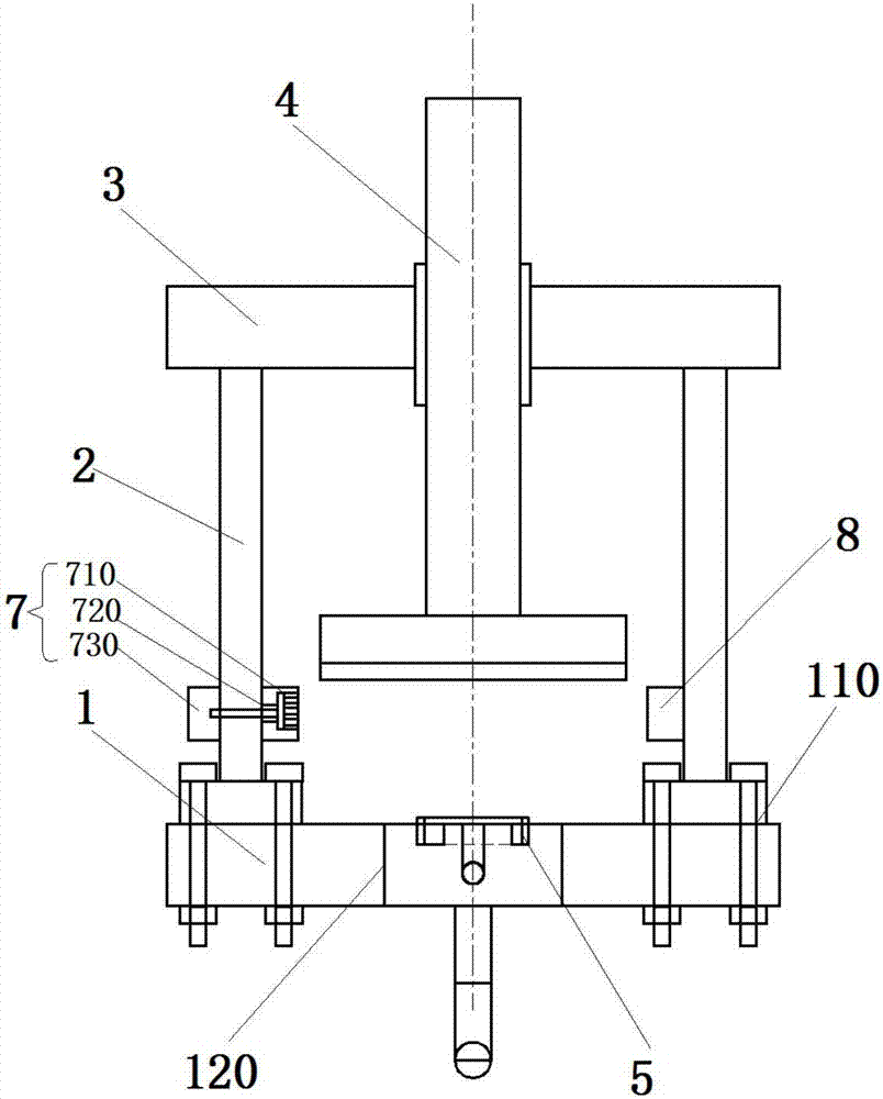
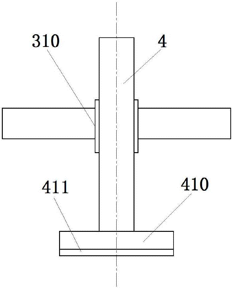
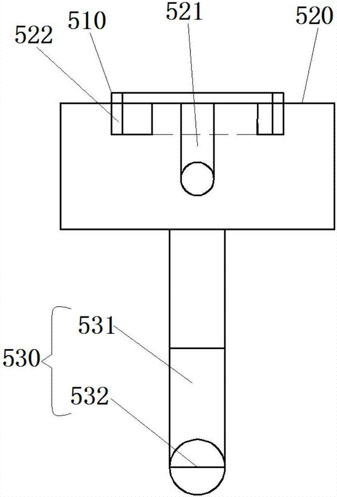
[0029] Please refer to Figure 1-Figure 4 , figure 1 Provide a schematic diagram of the overall structure of a part air tightness detection device for the present invention; figure 2 Provide a schematic diagram of the installation structure of the tooling mechanism for the present invention; image 3 A schematic diagram of the installation structure of the hydraulic action rod is provided for the present invention; Figure 4 A schematic diagram of the framework of the detection system is provided for the present invention.

[0030] Specifically, this embodiment provides a device for detecting air tightness of parts, which includes from bottom to top: a bottom plate 1, a support rod 2, an upper connecting plate 3, a hydraulic operating rod 4, and a tooling mechanism 5; wherein, the bottom plate 1 There are support rod mounting threaded holes 110 symmetrically arranged on both sides of the base plate 1; a through hole 120 is processed at the center of the base plate 1; the l...

Embodiment 2

[0041] Please refer to Figure 5 , Figure 5 The present invention provides a flow chart of a method for detecting the airtightness of parts.

[0042] Specifically, this embodiment provides a method for detecting air tightness of parts, using the device for detecting air tightness of parts described in Embodiment 1, including the following steps:

[0043] Step1, according to the shape of the detected part, select the corresponding mounting slot for the outer contour of the detected workpiece; and adjust the pressure regulating valve of the overpressure protection mechanism;

[0044] Step2, place the workpiece on the installation card slot for detecting the outer contour of the workpiece, press the hydraulic action lever down to compress the workpiece, start the gas compressor, open the two-position two-way manual valve, and the three-position three-way valve to inflate the container , pressure gauge 1 and pressure gauge 2 display the inflation pressure;

[0045] Step3, afte...


PUM


Abstract

The invention discloses a part air tightness detection device and a detection method thereof, which sequentially comprise from bottom to top: a base plate, a support rod, an upper connecting plate, a hydraulic action rod, and a tooling mechanism; wherein, the two sides of the base plate are arranged symmetrically There is a threaded hole for installing the support rod; a through hole is processed at the center of the bottom plate; the tooling mechanism includes: a mounting slot for detecting the outer contour of the workpiece, a tooling platform, and an overvoltage protection mechanism; the center position of the tooling platform is An air inlet installation hole is provided; the upper end surface of the tooling platform is provided with a detection workpiece outer contour installation card slot installation position; the detection workpiece outer contour installation card slot passes through the detection workpiece set on the upper end surface of the tooling platform The outer contour installation card slot installation position is fixedly installed on the upper end surface of the tooling platform; the overpressure protection mechanism includes: a hydraulic rod, and a pressure regulating valve; the pressure regulating valve is used to control the bearing pressure of the hydraulic rod .

Description

technical field [0001] The invention relates to the field of mechanical equipment, in particular to a component air tightness detection device and a detection method thereof. Background technique [0002] ​The air tightness test of parts is often encountered in industrial production. At present, the air tightness test of parts is mostly manual visual inspection method, that is, put the part into the liquid to inflate, and then observe whether the outer surface of the part is There are air bubbles leaking; in addition, there are some special mechanical testing equipment, but they are not perfect and mature. The main aspects are that the testing results are not accurate enough, the installation sealing is not enough, and the parts installation protection is not enough, which leads to inaccurate measurement results. Accurate, and the workpiece is damaged during the measurement process. In view of the above problems, the applicant has developed a part air tightness detection de...

Claims


Application Information

Patent Timeline
Patent Type & Authority Applications(China)
IPC IPC(8): G01M3/26G05D16/14
CPCG01M3/26G05D16/14
Inventor 刘丽华
Owner 刘丽华
Why Eureka
Try Eureka