

Magnetic drive generator and power generation system
A generator and magnetic transmission technology, applied in the direction of engine components, machines/engines, electrical components, etc., can solve problems such as potential safety hazards, difficulty in heat dissipation, failure to meet safety standards, etc., and achieve the effect of reducing air leakage
- Summary
- Abstract
- Description
- Claims
- Application Information
AI Technical Summary
Problems solved by technology
Method used
Image

Examples
no. 1 example
[0029] This embodiment provides a power generation system (not shown in the figure), which includes an electrically connected magnetic drive generator 100a and lead wires, and the lead wires are electrically connected to power supply equipment or power storage devices.
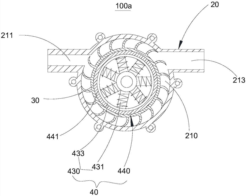
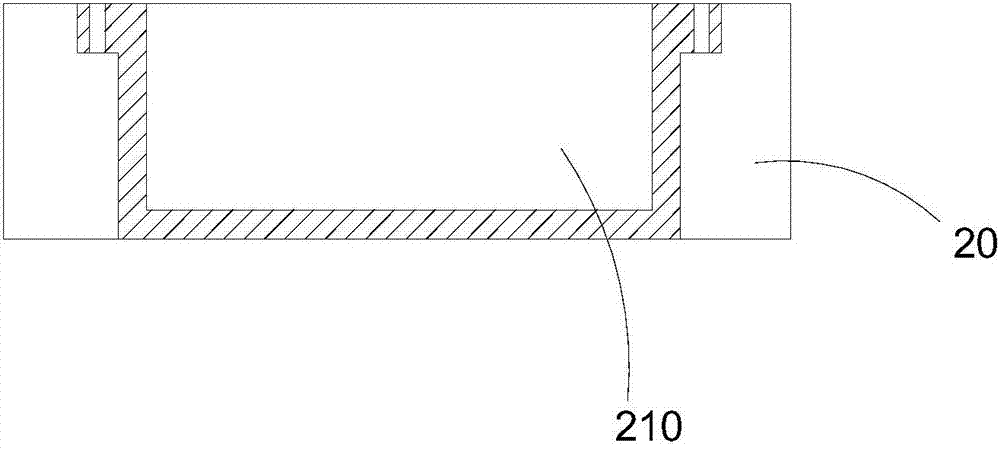
[0030] Specifically, see figure 1 , the magnetic drive generator 100 a includes a pipe 20 , an impeller 30 and a power generating device 40 . The pipeline 20 may be a pipeline with differential pressure, or a pipeline with equal pressure, which is not specifically limited here.
[0031] Please also refer to figure 1 as well as figure 2 , the pipeline 20 communicates with the accommodation chamber 210, and the two ends of the pipeline 20 corresponding to the accommodation chamber 210 have a diversion inlet 211 and a diversion outlet 213, so that the fluid in the pipeline 20 enters the accommodation chamber 210 through the diversion inlet 211, and finally passes through the diversion outlet 213 outflow. The...
no. 2 example
[0050] Please refer to Image 6 , the present embodiment provides a magnetic drive generator 100b, which is similar in structure to the magnetic drive generator 100a provided in the first embodiment, the difference is that the impeller 30, the generator 40, and the gap between the generator 40 and the impeller 30 cooperation relationship.
[0051] The rotor 440 includes a first rotor 441 and a second rotor 443 .
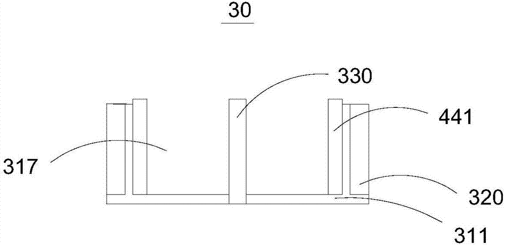
[0052] Wherein, the first rotor 441 is arranged on at least one side of the impeller body 311 along its rotation direction, specifically, the first rotor 441 is arranged along the circumference of at least one end of the impeller body 311. It should be noted that the impeller 30 is also It can be set as the first rotor 441 as a whole, that is, the impeller 30 is made of magnetic material as a whole.
[0053] In this embodiment, the first rotor 441 is arranged at both ends of the impeller body 311,
[0054] Effectively reduce the use of magnetic materials, prevent ...
no. 3 example
[0068] Please refer to Figure 9 , the present embodiment provides a magnetic drive generator 100c, which is substantially the same as the magnetic drive generator 100a of the first embodiment, the difference between the two lies in the power generating device 40, the impeller 30 and the cooperation between the two in this embodiment relation.
[0069] The axes of the diversion inlet 211 and the diversion outlet 213 can be arranged in parallel, coincident or at an angle. In this embodiment, the axes of the diversion inlet 211 and the diversion outlet 213 are arranged at an angle.
[0070] The first rotor 441 is disposed on the side of the impeller 30 away from the housing cavity 210 , and the shape of the first rotor 441 can be set in various geometric shapes according to specific torque requirements, which is not limited here.
[0071] In order to further fix the impeller 30, it is preferable that a fixing sleeve 215 is provided in the accommodating chamber 210,
[0072] Th...
PUM
 Abstract
Description
Claims
Application Information