A method of machining a workpiece and a linear hammer

A technology for processing workpieces and linearity, applied in the field of linear hammers, can solve the problems of small application range and high cost of forging hammers, and achieve the effects of reduced waste, repeatable quality, and expanded application range

Active Publication Date: 2017-07-28
SCHULER PRESSEN GMBH & CO KG
View PDF6 Cites 0 Cited by
  • Summary
  • Abstract
  • Description
  • Claims
  • Application Information

AI Technical Summary

Problems solved by technology

In addition to the smaller scope of application of the forging hammer, it is also disadvantageous that correspondingly higher costs arise due to the additional mechanism

Method used


Image

  • A method of machining a workpiece and a linear hammer
  • A method of machining a workpiece and a linear hammer
  • A method of machining a workpiece and a linear hammer

Examples


Embodiment Construction

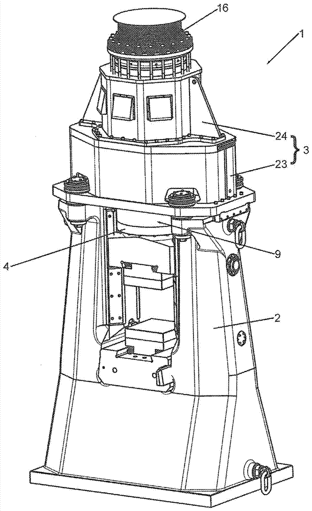
[0086] figure 1 A perspective illustration of the linear hammer 1 is shown. It comprises an anvil 2 which has a U-like profile. A head section 3 is arranged on the anvil 2 . In the exemplary embodiment shown, the head section 3 is composed of a lower head section 23 and an upper head section 24 .

[0087] In a manner not shown further, the header section 3 can also be designed in one piece.

[0088] A cover 16 is arranged on the head section 3 or on the upper head section 24 . A striker 4 is formed in the anvil 2 . The linear hammer 1 comprises an upper part 7 of a forging die 6 and a lower part 5 of the forging die 6 for machining a workpiece (not shown).

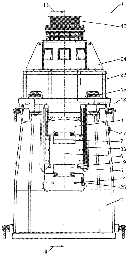
[0089] exist figure 2 is shown in schematic side view already in figure 1 The linear hammer shown in 1. The linear hammer 1 is here designed as a short-stroke die hammer. The linear hammer 1 comprises the mentioned anvil 2 , an anvil insert 14 , a head section 3 and a hammer head 4 .

[0090] The head section 3 ...


PUM


Abstract

The invention relates to a method of machining a workpiece and a linear hammer, and particularly provides a method of machining a workpiece by utilizing a linear hammer (1), wherein the linear hammer (1) applies at least two deformation processes on the workpiece and at least one deformation process includes an extruding process.

Description

technical field [0001] The invention relates to a method for machining a workpiece with a linear hammer according to the preamble of claim 1 or 5 and a linear hammer according to the preamble of claim 11 . Background technique [0002] Forging hammers for use in industry, for example in free-form forging or in die forging, are sufficiently known from the prior art. A detailed introduction about this specialized field can be found in the document "Handbook Retrofit Technology", Eckhart Doege, Bernd-Arno Behrens, Springer Verlag, 2nd edition, 2010, pages 719 and subsequent pages (Literatur "Handbuch Umformtechnik”, Eckhart Doege, Bernd-Arno Behrens, Springer-Verlag, 2. Auflage, 2010, Seiten 719 ff.). [0003] The prior art from DE 20 2014 104 509 U1 also discloses forging hammers which are driven by linear motors and are thus designed as so-called linear hammers. Such a linear hammer can advantageously be controlled manually in a particularly simple and extensive manner. ...

Claims


Application Information

Patent Timeline
Patent Type & Authority Applications(China)
IPC IPC(8): B21J7/22B21J7/04B21J13/02B21J13/06B21J5/02
CPCB21J5/02B21J7/04B21J7/22B21J13/02B21J13/06B21J7/30B21J7/46B21J9/022B21J11/00B21J13/04B30B1/00B30B1/42B30B15/065
Inventor M.贝洛赫R.博普A.德雷赫尔
Owner SCHULER PRESSEN GMBH & CO KG
Why Eureka
Try Eureka