Light-typed pipe cutting chuck

A cutting tube clamping and light-weight technology, which is applied in the direction of chucking, clamping, supporting, etc., can solve the problems of heavy chuck, easy failure, and low precision, and achieve good synchronization, precision assurance, and convenient maintenance.

Active Publication Date: 2017-07-28
俞雪清
View PDF9 Cites 22 Cited by
  • Summary
  • Abstract
  • Description
  • Claims
  • Application Information

AI Technical Summary

Problems solved by technology

[0004] The technical problem to be solved by the present invention is: in order to solve the above-mentioned technical problems of the

Method used


Image

  • Light-typed pipe cutting chuck
  • Light-typed pipe cutting chuck
  • Light-typed pipe cutting chuck

Examples


Embodiment Construction

[0020] The present invention is described in further detail now in conjunction with accompanying drawing. These drawings are all simplified schematic diagrams, which only illustrate the basic structure of the present invention in a schematic manner, so they only show the configurations related to the present invention.

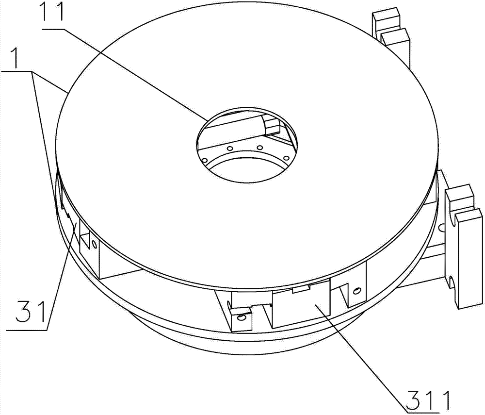
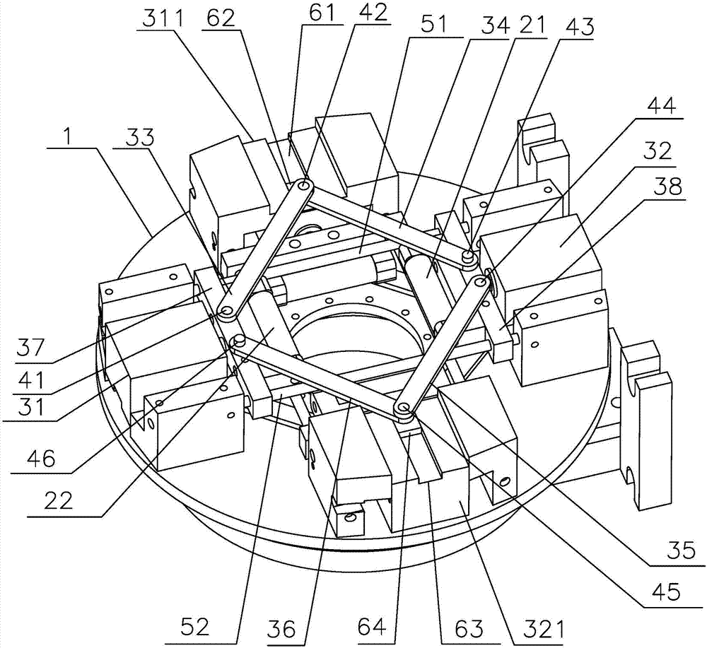
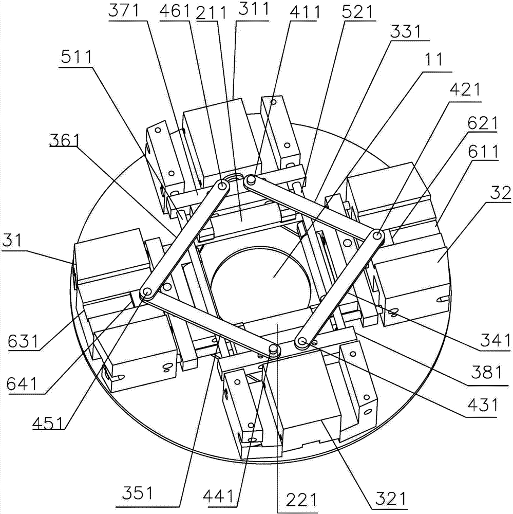
[0021] like Figure 1-3 As shown, it is the best embodiment of the present invention, a light-duty pipe cutting chuck, including a motherboard 1, and a through hole 11 is provided in the middle of the motherboard 1 to allow pipe fittings to pass through. Pneumatic clamps for pipes passing through the through holes 11, the pneumatic clamps include multiple pairs of clamp bars and a double-hinge type clamp bar pneumatic drive mechanism that independently controls the movement of each pair of clamp bars toward or against each other.

[0022] This embodiment takes two pairs of clamp rods and two double-hinge type clamp rod pneumatic drive mechanisms as examples f...


PUM


Abstract

The invention relates to the technical field of pipe fitting fixture, in particular to a light-typed pipe cutting chuck. The chuck comprises a master plate. The middle part of the master plate is provided with a through hole, wherein pipe fittings can penetrate through the through hole; a pneumatic clamp is arranged on the master plate, wherein the pneumatic clamp can hold the pipe fittings penetrating through the through hole. The pneumatic clamp comprises a plurality of pairs of clamp bars and a double hinged type clamping rod pneumatic drive mechanism which independently controls the same or opposite movement of each pair of the clamp bars. According to the light-typed pipe cutting chuck, through four connecting rods (double hinged type), the good synchronism of a first cylinder and a second cylinder can be ensured; the precision is greatly protected; most of materials of the light-typed pipe cutting chuck are aluminum materials, thus the weight is reduced at least 65% compared with the weight of the conventional structure using steel materials; the existing T-typed slot is replaced by a guide rod, thereby avoiding the phenomenon of the claw locking because of the dust accumulation in the T-typed slot; movable structures are all placed outside; the fault is judged easily; the maintenance is more convenient.

Description

technical field [0001] The invention relates to the technical field of pipe fixtures, in particular to a light-duty pipe cutting chuck. Background technique [0002] The principle of pipe cutting machine and pipe welding machine is through the mutual cooperation of computer and hydraulic pressure, and the electric system controls the oil circuit movement direction of the hydraulic system, and pushes the carriage to make linear reciprocating motion. The microcomputer will walk according to the user-edited cutting route. During the reciprocating movement, the signal detected by the carriage limit is used as a basis to control and change the movement of its oil circuit, so as to achieve the expected cutting route. [0003] Because the chucks currently on the market have various disadvantages in the application of pipe cutting, their functions or performance are not perfect, and they can only be said to barely cope with their use. For example, the pneumatic type: the efficiency...

Claims


Application Information

Patent Timeline
IPC IPC(8): B23B31/02B23Q3/00
CPCB23B31/02B23Q3/00B23Q2703/04B23Q2703/10
Inventor 俞雪清
Owner 俞雪清
Why Eureka
Try Eureka