Polishing device and automatic metallurgical polishing machine

A technology of polishing device and polishing machine, which is applied in the direction of surface polishing machine tools, grinding drive devices, grinding/polishing equipment, etc., can solve problems such as difficulties and uncertainty of artificial polishing accuracy, and achieve low device cost and convenient installation. The effect of tearing down

Inactive Publication Date: 2017-07-28
东北大学秦皇岛分校
View PDF6 Cites 8 Cited by
  • Summary
  • Abstract
  • Description
  • Claims
  • Application Information

AI Technical Summary

Problems solved by technology

[0005] The purpose of the present invention is to: provide a polishing device and an automatic metallographic polishing mach

Method used


Image

  • Polishing device and automatic metallurgical polishing machine
  • Polishing device and automatic metallurgical polishing machine
  • Polishing device and automatic metallurgical polishing machine

Examples


Embodiment 1

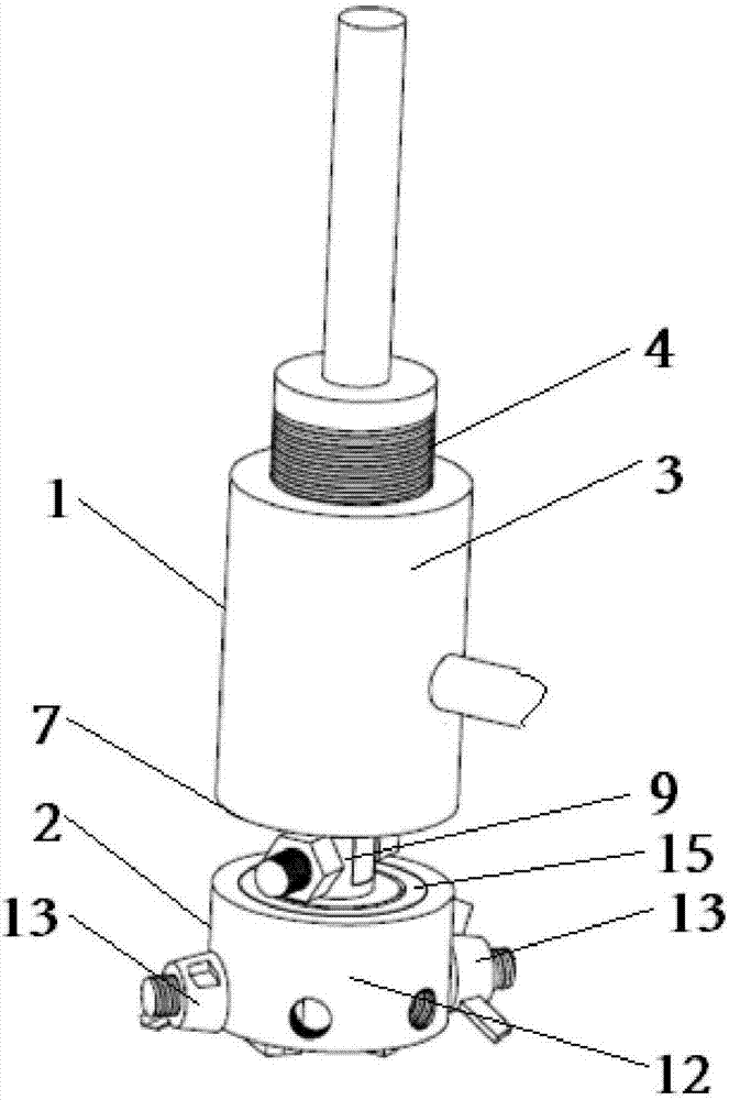
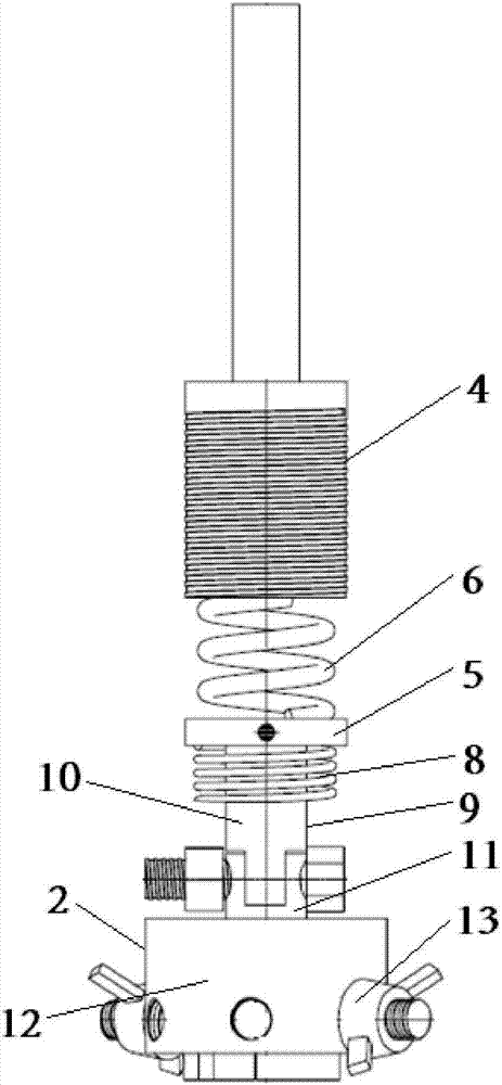
[0028] see figure 1 with figure 2 As shown, a polishing device includes a feed mechanism 1 and a clamping mechanism 2, and the feed mechanism is connected to the clamp mechanism; the feed mechanism includes a housing 3 and an extrusion head 4, and the extrusion The indenter is connected to the housing through threads, and the housing is floatingly connected to the polishing turntable through a support frame. The support frame is slidingly connected to a guide groove arranged on the central axis of the polishing turntable. There is a buffer spring; the housing is provided with a sliding partition 5, and the sliding partition is slidably connected with the box body; an extrusion spring 6 is arranged between the extrusion head and the sliding partition, and the The sliding partition is connected with the clamping mechanism. A sealing plate 7 is provided at the end of the housing opposite to the extrusion head, the sealing plate is fixed to the housing, and a support spring 8 i...

Embodiment 2

[0030] Embodiment 2. This embodiment is improved on the basis of Embodiment 1. The content described in Embodiment 1 is also included in this embodiment, and will not be repeated here.

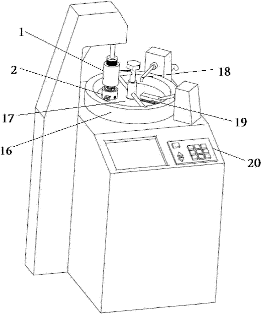
[0031] see image 3 with Figure 4 As shown, an automatic metallographic polishing machine is also provided in this embodiment, including the polishing device; the automatic metallographic polishing machine also includes a polishing turntable 16, and the polishing turntable corresponds to the position of the polishing device Setting, a polishing cloth 17 is arranged inside the polishing turntable. The automatic metallographic polishing machine also includes a water inlet mechanism 18 and a cleaning mechanism 19, and the water inlet mechanism and the cleaning mechanism are arranged corresponding to the positions of the polishing turntable. The automatic metallographic polishing machine also includes a controller 20, and the power mechanism is electrically connected to the controller. The con...


PUM


Abstract

The present invention relates to the technical field of metallographic polishing equipment, in particular to a polishing device and an automatic metallographic polishing machine; the polishing device includes a feeding mechanism and a clamping mechanism, and the feeding mechanism is connected to the clamping mechanism; The feed mechanism includes a housing and an extrusion head, and the extrusion head is connected to the housing through threads; a sliding partition is provided in the housing, and the sliding partition is slidingly connected to the box body; An extrusion spring is arranged between the extrusion head and the sliding partition, and the sliding partition is connected with the clamping mechanism. In the polishing device and the automatic metallographic polishing machine disclosed in the present invention, firstly, the extrusion head part is controlled by thread, which has high precision and is easy to control; the innovative use of springs to realize the force feeding realizes the gradual change of the force and satisfies the test requirements. The polishing requirements of the sample; the bearing is installed at the bottom clamping device, so that the sample can not only revolve with the polishing cloth, but also rotate, so that the sample can be polished more ideally.

Description

technical field [0001] The invention relates to the technical field of metallographic polishing equipment, in particular to a polishing device and an automatic metallographic polishing machine. Background technique [0002] In industrial production, it is often necessary to use a polishing device to polish the workpiece. The polishing operation usually generates a large amount of heat, and in order to prevent the workpiece from being deformed due to the heat generated, or to avoid the processing accuracy being affected by the heat, the polishing device is also provided with a jet pipe, and the bottom of the polishing device is provided with a There is the sump body. The spray pipe is used for spraying polishing fluid to cool the workpiece. However, the periphery of the concentrated liquid tank is closed, which is not conducive to the outflow of the polishing liquid. After the workpiece is polished by the polishing device, subsequent inspection operations are required. Whe...

Claims


Application Information

Patent Timeline
IPC IPC(8): B24B29/02B24B41/06B24B47/20G01N1/32
CPCB24B29/02B24B41/06B24B47/20G01N1/32
Inventor 梅瑞斌闫鹏飞包立张进马家宾周家安
Owner 东北大学秦皇岛分校
Why Eureka
Try Eureka