Polishing device

A grinding machine and grinding wheel technology, which is applied in the direction of grinding/polishing safety devices, grinding machine parts, grinding/polishing equipment, etc., can solve the problems of safety hazards, grinding personnel injuries, etc., and achieve high safety and reduce Small safety hazard, uniform force effect

Active Publication Date: 2017-07-28
江门市新会新鸿达五金制品有限公司
View PDF7 Cites 2 Cited by
  • Summary
  • Abstract
  • Description
  • Claims
  • Application Information

AI Technical Summary

Problems solved by technology

However, the existing workpiece grinding devices are often directly connected with the grinding wheel and the motor. If the motor is accidentally turned on, it is easy to cause injury to the grinding personnel, and after the grinding is completed, the grinding wheel will continue to rotate for a period of time due to inertia. Therefore, the common grinding device There is a great security risk

Method used


Image

  • Polishing device
  • Polishing device
  • Polishing device

Examples


Embodiment Construction

[0020] All features disclosed in this specification, or steps in all methods or processes disclosed, may be combined in any manner, except for mutually exclusive features and / or steps.

[0021] Any feature disclosed in this specification (including any appended claims, abstract and drawings), unless expressly stated otherwise, may be replaced by alternative features which are equivalent or serve a similar purpose. That is, unless expressly stated otherwise, each feature is one example only of a series of equivalent or similar features.

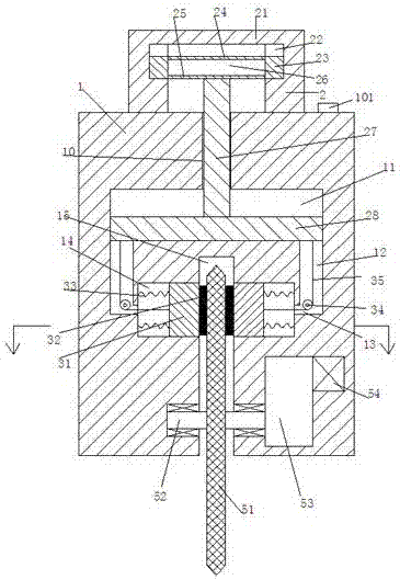
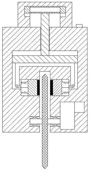
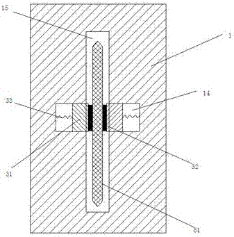
[0022] Such as Figure 1-3 As shown, a grinding device of the present invention includes a grinding machine 1 and a grinding wheel 51. A frame body 2 is fixedly arranged at the left and right ends of the upper end surface of the grinding machine 1, and a handle bar is fixedly arranged between the two frame bodies 2. 21. A first sliding groove 22 is arranged in the inner end surface of each frame body 2, and a sliding block 23 is installed in ...


PUM


Abstract

A polishing device comprises a polishing machine and a polishing wheel. Two racks are fixedly arranged at the left end and the right end of the upper end face of the polishing machine. A handheld rod is fixedly arranged between the two racks. The inner side end face of each rack is provided with a first sliding pushing groove. Two sliding pushing blocks are installed in each first sliding pushing groove and can vertically move. A pulling-up rod and a connecting arm rod are fixed between the two sliding pushing blocks. A cavity is formed in the center of the polishing machine. A hole groove is formed in the center of the upper end wall of the cavity. A sliding pushing plate is installed in the cavity and can vertically move. A connecting shaft is installed in the hole groove and can vertically move. The lower end of the connecting shaft is fixedly connected with the sliding pushing plate. The upper end of the connecting shaft is fixedly connected with the connecting arm rod. The two side walls of an assembly groove are correspondingly provided with second sliding pushing grooves. The left side and the right side of the lower end wall of the cavity are correspondingly provided with first through grooves. Communicating second through grooves are formed between the first through grooves and the second sliding pushing grooves. Locking blocks are installed in the second sliding pushing grooves and can move leftwards and rightwards.

Description

technical field [0001] The invention relates to the technical field of grinding, in particular to a grinding device. Background technique [0002] Workpiece grinding is an important process in the process of workpiece processing. It mainly uses the high-speed rotation of the grinding wheel to grind and polish the fine particles or unevenness on the surface of the workpiece. However, the existing workpiece grinding devices are often directly connected with the grinding wheel and the motor. If the motor is accidentally turned on, it is easy to cause injury to the grinding personnel, and after the grinding is completed, the grinding wheel will continue to rotate for a period of time due to inertia. Therefore, the common grinding device There are great security risks. Contents of the invention [0003] The object of the present invention is to provide a grinding device capable of overcoming the above-mentioned defects of the prior art. [0004] According to the present inven...

Claims


Application Information

Patent Timeline
Patent Type & Authority Applications(China)
IPC IPC(8): B24B55/00B24B49/16
CPCB24B49/165B24B55/00
Inventor 陈柯
Owner 江门市新会新鸿达五金制品有限公司
Why Eureka
Try Eureka