Motor seat capable of changing tilt angles of rotor surfaces of multi-rotor unmanned aerial vehicle

A multi-rotor unmanned and aircraft rotor surface technology, which is applied to the tilt angle control of the multi-rotor UAV rotor surface and the field of multi-rotor UAV rotor control, can solve the problems of UAV spin, uncontrolled fall, etc., to achieve The effect of avoiding spin, reducing the difference, and facilitating the adjustment of balance

Active Publication Date: 2017-07-28
SICHUAN COLLEGE OF ARCHITECTURAL TECH
View PDF29 Cites 11 Cited by
  • Summary
  • Abstract
  • Description
  • Claims
  • Application Information

AI Technical Summary

Problems solved by technology

[0005] The purpose of the present invention is to provide a motor seat that can change the inclination angle of the rotor surface of the multi-rotor UAV, which is used to solve the problem that the UAV will spin or rotate when one rotor of the multi-rotor UAV fails in the prior art. The problem of falling out of control

Method used


Image

  • Motor seat capable of changing tilt angles of rotor surfaces of multi-rotor unmanned aerial vehicle
  • Motor seat capable of changing tilt angles of rotor surfaces of multi-rotor unmanned aerial vehicle
  • Motor seat capable of changing tilt angles of rotor surfaces of multi-rotor unmanned aerial vehicle

Examples


Embodiment 1

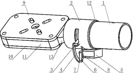
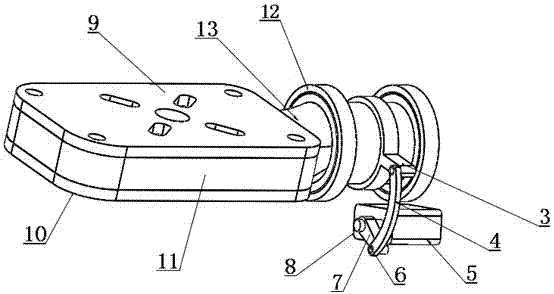
[0030] combined with figure 1 and 2 As shown, a motor base that can change the inclination angle of the rotor surface of a multi-rotor UAV includes a motor mounting plate 9, an ESC mounting plate 10, and a mounting plate seat for fixedly installing the motor mounting plate 9 and the ESC mounting plate 10 11. The mounting plate base 11 is provided with a deflection tube 13 that is fixedly connected or integrally formed. The deflection tube 13 is fixedly connected with a pull ring 3 with arms. The fixed sleeve 1 of the machine arm, the middle part of the fixed sleeve 1 is provided with an arc-shaped opening along the circumferential direction, and the arm pull ring 3 is provided with a protruding arm, and the protruding arm can rotate in the arc-shaped opening , the outer surface of the fixed sleeve 1 is provided with a protruding steering gear mounting plate 8, and a steering gear 5 is mounted on the steering gear mounting plate 8, and the steering gear 5 is drivingly connecte...

Embodiment 2

[0036] Such as Figure 1-3 As shown, on the basis of Embodiment 1, the fixed sleeve 1 is a stepped shaft sleeve, most of the fixed sleeve 1 is the bearing sleeve 2 socketed with the deflection tube 13, and the bearing sleeve 2 and the deflection tube 13 is provided with a bearing 12, and the steering gear mounting plate 8 is fixedly connected or integrally formed with the bearing sleeve 2. By arranging the bearing sleeve 2 and the bearing 12, the friction force when the deflection tube 13 rotates is reduced, the rotation is smoother, and the control performance of the drone is enhanced.

[0037] Further, the output end of the steering gear 5 is equipped with a steering gear rocker arm 7, and the steering gear rocker arm 7 drives and connects a pull rod 4, and the pull rod 4 is hinged to the convex arm of the arm pull ring 3.

[0038] Further, the central angle corresponding to the arc-shaped opening on the bearing sleeve 2 is 0°-90°, so that the rotatable angle of the pull ri...


PUM


Abstract

The invention discloses a motor seat capable of changing the tilt angles of the rotor surfaces of a multi-rotor unmanned aerial vehicle and relates to the field of control over the tilt angles of the rotor surfaces of multi-rotor unmanned aerial vehicles. The motor seat comprises a motor mounting plate, an electronic speed control mounting plate and a mounting plate seat; a deflection pipe is fixed on the mounting plate seat; a belt arm pull ring is fixedly connected on the deflection pipe; the deflection pipe is sleeved with a fixing sleeve for connecting an unmanned aerial vehicle arm; the fixing sleeve is provided with an arc-shaped opening in the central circumferential direction; a convex arm of the belt arm pull ring can rotate along the arc-shaped opening of the fixing sleeve; and the belt arm pull ring is in driving connection with a steering engine. According to the motor seat, the motor mounting plate is arranged to be a rotatable structure, when one rotor is in failure, the tilt angle of the rotor surface of the corresponding normal rotor is adjusted, and then rising force can be converted to the force resisting automatic rotation, so that the problem that in the prior art, when one rotor of a multi-rotor unmanned aerial vehicle is in failure, the unmanned aerial vehicle automatically rotates or loses control and falls down is solved.

Description

technical field [0001] The invention relates to the field of multi-rotor UAV rotor control, in particular to the field of multi-rotor UAV rotor surface inclination angle control, specifically, a motor base capable of changing the multi-rotor UAV rotor surface inclination angle. Background technique [0002] UAV is the abbreviation of "unmanned aircraft", and the English abbreviation is "UAV". It is an unmanned aircraft controlled by radio remote control equipment and its own program control device. The concept of drones first appeared in the 1920s. With the rapid development of science and technology, the technology of drones has become more and more mature, and the application of drones has gradually entered the public eye. , drones + industry applications are the real needs of drones today. At present, it is widely used in aerial photography, agriculture, plant protection, micro selfie, express delivery, disaster relief, observation of wild animals, monitoring of infectio...

Claims


Application Information

Patent Timeline
Patent Type & Authority Applications(China)
IPC IPC(8): B64C27/52B64C27/32
CPCB64C27/32B64C27/52B64U10/10Y02T50/40
Inventor 谢明阳
Owner SICHUAN COLLEGE OF ARCHITECTURAL TECH
Why Eureka
Try Eureka