Supercharge Your Innovation With Domain-Expert AI Agents!

A device for monitoring product components in the plume region of a Hall thruster

A Hall thruster and plume technology, which is applied in the field of monitoring the product components of Hall thrusters, can solve problems such as spacecraft corrosion, communication influence, and charge accumulation, and achieve the effect of avoiding interference.

Active Publication Date: 2019-06-11
HARBIN INST OF TECH
View PDF4 Cites 0 Cited by
  • Summary
  • Abstract
  • Description
  • Claims
  • Application Information

AI Technical Summary

Problems solved by technology

[0004] 1. The collision of neutral gas and fast ions will produce slow ions, which will be accelerated radially and flow back to the front of the thruster, causing corrosion and charge accumulation to the spacecraft
[0005] 2. Since the plume of the Hall thruster is in a plasma state, it has a shielding effect on electromagnetic waves, which may affect the communication on the spacecraft

Method used


Image

  • A device for monitoring product components in the plume region of a Hall thruster
  • A device for monitoring product components in the plume region of a Hall thruster

Examples


specific Embodiment approach 1

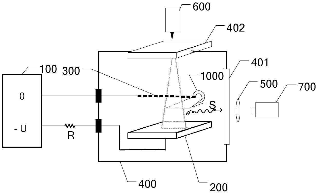
[0021] Specific implementation mode 1: Combination figure 1 To describe in detail this embodiment, a device for monitoring the product components of the plume area of ​​a Hall thruster includes a high-voltage power supply 100, a cathode plate 200, an electrode 300, a vacuum chamber 400, a filter 500, a nanosecond pulse laser 600, and ICCD Camera 700 and computer 800;

[0022] The cathode plate 200 is opposite to the electrode 300 and is arranged in parallel in the vacuum chamber 400, the Hall thruster plume area is located in the area between the cathode plate 200 and the electrode 300, and the bias voltage output terminal of the high voltage power supply 100 is connected through the resistor R. The cathode plate 200, the zero potential output terminal of the high voltage power supply 100 is connected to the electrode 300;

[0023] The laser light emitted by the nanosecond pulse laser 600 is incident perpendicular to the cathode plate 200 through the second window 402. The jet dire...

specific Embodiment approach 2

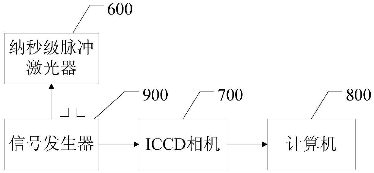
[0028] Specific implementation manner two: combination figure 2 This embodiment is described in detail. This embodiment is to further explain the device for monitoring the product components in the plume area of ​​the Hall thruster described in the first embodiment. In this embodiment, the signal is also included in this embodiment. The generator 900 and the rectangular signal output by the signal generator 900 trigger the nanosecond pulse laser 600 and the ICCD camera 700 synchronously.

[0029] The ICCD camera and laser are controlled by the same signal generator. The signal generator generates a rectangular wave with a frequency of 100-1000 Hz. The rectangular signal generated by the signal generator is input to the solid-state laser and ICCD, and the laser and ICCD are triggered synchronously. The fluorescence signal captured by ICCD is input into the computer and saved.


PUM


Abstract

Relating to the monitoring technology of Hall effect thruster product components, the invention relates to a device for monitoring Hall effect thruster plume region product components to meet the need for analysis of Hall effect thruster plume region product components. A negative plate and an electrode are oppositely and parallelly disposed in a vacuum chamber, a Hall effect thruster plume region is located in an area between the negative plate and the electrode, a bias voltage output end of a high voltage power supply is connected to the negative plate, and a zero potential output end of the high voltage power supply is connected to the electrode. Laser emergent from a nanosecond pulse laser is vertically incident to the negative plate, the jet flow direction of a negative plate escape electron beam is perpendicular to the Hall effect thruster plume jet direction, electrons collide with plume region particles to generate fluorescence, an ICCD camera collects fluorescence through a filter, and the ICCD camera is connected to a computer. The device provided by the invention is suitable for monitoring the Hall effect thruster plume region product components.

Description

Technical field [0001] The invention relates to the monitoring technology of the product components of the Hall thruster. Background technique [0002] As satellites put forward higher requirements for life, the increase in the life of satellite thrusters has become the key. The traditional satellite chemical thruster has a large thrust but a small specific impulse. To increase the life of the thruster, the chemical fuel carried by the satellite must be increased, which increases the satellite launch cost and reduces the effective load. Compared with traditional chemical thrusters, electric thrusters have the advantages of small size, light weight, high specific impulse, and long life. They can reduce the cost of satellite launch and can meet the requirements of the life of the satellite, which has become a research focus of various countries. [0003] At present, Hall thrusters and ion thrusters are the mainstay. Hundreds of electric thrusters have been applied to satellites, mai...

Claims


Application Information

Patent Timeline
Patent Type & Authority Patents(China)
IPC IPC(8): G01N21/64
CPCG01N21/6402
Inventor 朱悉铭宁中喜刘晨光韩星孟圣峰王彦飞
Owner HARBIN INST OF TECH
Features
  • R&D
  • Intellectual Property
  • Life Sciences
  • Materials
  • Tech Scout
  • Unparalleled Data Quality
  • Higher Quality Content
  • 60% Fewer Hallucinations
Learn More