A head-mounted human body input apparatus spatial position and attitude measuring method

A technology of input devices and spatial positions, applied in the field of sensors, can solve problems such as cursor drift, affecting user experience, and difficult to completely remove offsets

Inactive Publication Date: 2017-07-28
陕西硕轩信息科技有限公司
View PDF3 Cites 8 Cited by
  • Summary
  • Abstract
  • Description
  • Claims
  • Application Information

AI Technical Summary

Problems solved by technology

Since the output signal of the inertial navigation sensor contains a certain amount of offset, and the offset amount is difficult to completely remove, the positioning error of the mouse for the human input ...

Method used


Image

  • A head-mounted human body input apparatus spatial position and attitude measuring method
  • A head-mounted human body input apparatus spatial position and attitude measuring method
  • A head-mounted human body input apparatus spatial position and attitude measuring method

Examples


Embodiment 1

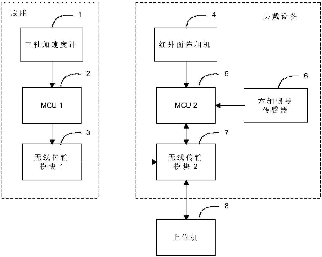
[0079] see figure 1 , 2 And 3, the present invention is realized by adopting the following technical solutions, a head-mounted human body input device space position and attitude measurement device, comprising:

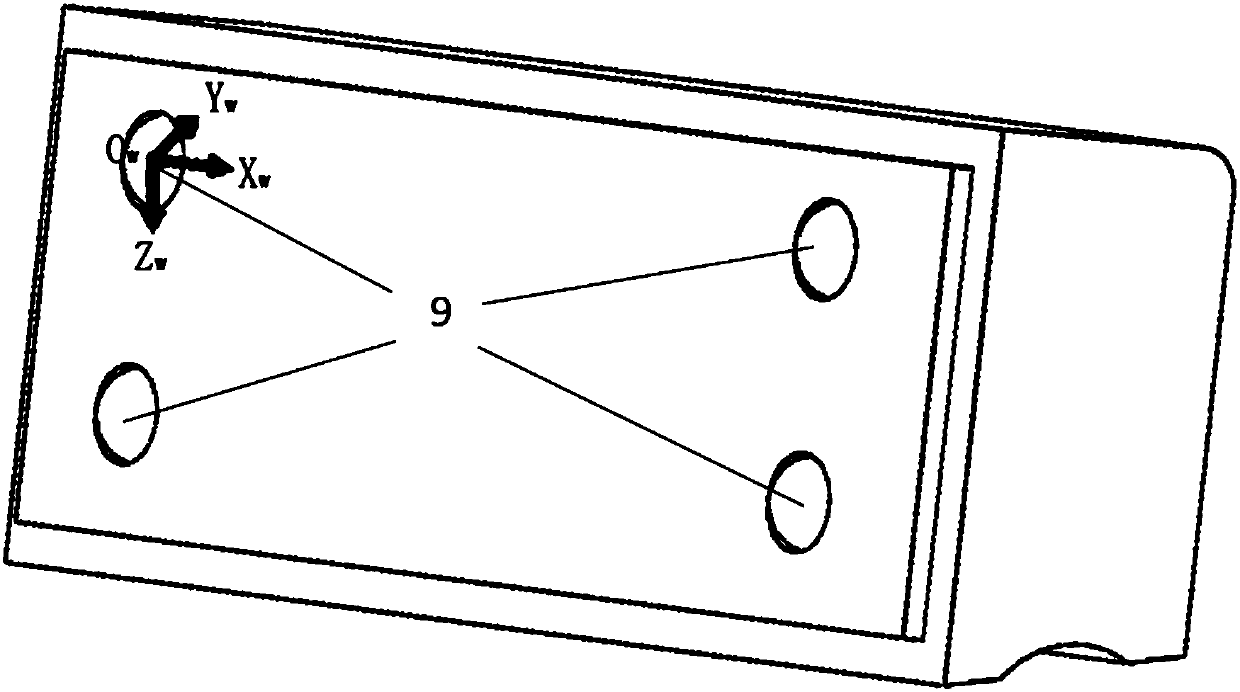
[0080] Infrared light emitting devices include:

[0081] Three-axis accelerometer (1), MCU 1 (2), wireless transmission module 1 (3), infrared light diode (9);

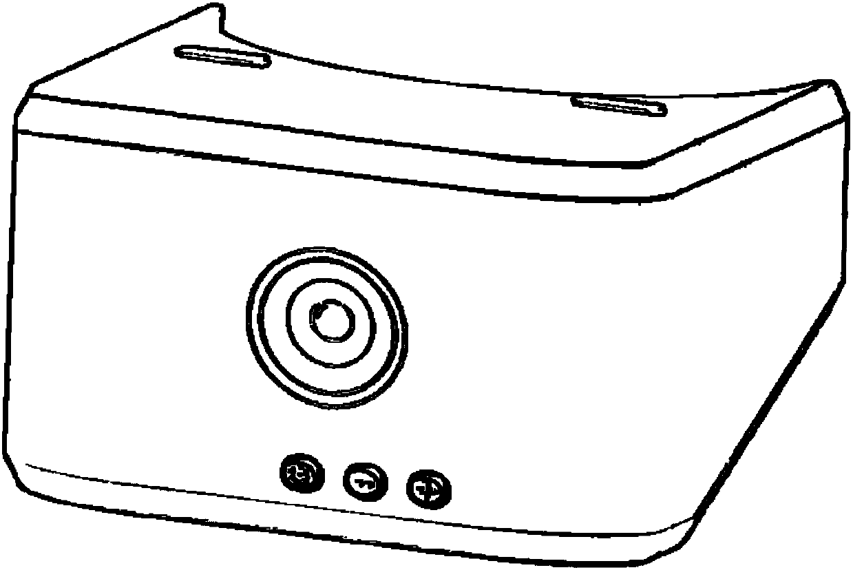
[0082] Headsets include:

[0083] Infrared area scan camera (4), MCU 2 (5), six-axis inertial navigation sensor (6), wireless transmission module 2 (7), upper computer (8).

[0084] in,

[0085] The three-axis accelerometer (1) is installed inside the infrared light emitting base, and is used to detect the pose relationship between the base and the world coordinate system;

[0086] The MCU 1 (2) is used to calculate the pose matrix of the infrared light emitting base and the world coordinate system according to the data measured by the triaxial accelerometer (1);

[0087] The wireless transmission modul...

Embodiment 2

[0099] Step 1, positioning the four infrared light spots emitted by the infrared light emitting device through the infrared area array camera installed on the head-mounted human body input device; the infrared light emitting device includes four infrared light source arrays;

[0100] Step 11, in the image coordinate system, edge detection is performed on the pixel point (u, v) in the image collected by the infrared area array camera, and the gray value G( u,v):

[0101]

[0102]

[0103]

[0104] Among them, f(u, v) is the gray value corresponding to the pixel point (u, v) in the image before edge detection;

[0105] The image coordinate system takes the upper left corner of the figure as the origin, the horizontal direction is the u axis, and the vertical direction is the v axis;

[0106] Step 12, setting the threshold T, if G(u, v) > T, then the pixel point (u, v) is the edge point of the infrared bright spot;

[0107] In this embodiment, the Otsu method is used t...

Embodiment 3

[0151] Since the infrared light emitting device may not be perpendicular to the horizontal plane, in order to avoid errors, this embodiment constructs a world coordinate system and calculates the pose matrix of the camera coordinate system relative to the world coordinate system. This embodiment is described in Embodiment 3 On top of that, it also includes:

[0152] Step 31, obtain the acceleration of gravity g from the three-axis accelerometer installed on the infrared light emitting device in the reference coordinate system X r component g on the axis xr , Y r component g on the axis yr ,Z r component g on the axis zr ;

[0153] Step 32, since the direction of gravity is always consistent with the Z of the world coordinate system w Axis coincidence, when the reference coordinate system rotates relative to the world coordinate system, g can be used xr , g yr , g zr , the pose matrix of the reference coordinate system relative to the world coordinate system is obtaine...


PUM


Abstract

The invention provides a head-mounted human body input apparatus spatial position and attitude measuring method. The method comprises the steps of collecting signals of an inertial sensor and first and second infrared area-array cameras; detecting whether the infrared area-array cameras detect infrared light feature structures. If infrared light feature structures are detected, a system inversely calculates spatial position and attitude parameters of a head-mounted apparatus via image information and update state parameters of the inertial sensor; if infrared light feature structures are not detected, the system measures spatial position and attitude parameters of the head-mounted apparatus according to newly-updated state parameters of the inertial sensor; finally, the system transmits the parameters to an upper computer which achieves more specific man-machine interaction operations.

Description

technical field [0001] The invention belongs to the technical field of sensors, in particular to a method for measuring the spatial position and attitude of a head-mounted human body input device. Background technique [0002] Due to the rise of emerging technologies such as the current virtual reality technology, people are no longer only satisfied with utilizing a traditional computer mouse to realize interactive control with a computer. At present, in order to realize actions in the virtual reality world, users still mainly complete them through traditional ergonomic input devices such as mouse, keyboard, and joystick. Because when the user is immersed in the virtual reality, the user cannot see the buttons of the mouse and the keyboard, thus affecting the user's experience effect. [0003] Currently disclosed head-mounted computer cursor control devices mainly rely on multi-axis inertial navigation to measure the spatial position and attitude parameters of the head-moun...

Claims


Application Information

Patent Timeline
IPC IPC(8): G06F3/01G06T7/70G06T7/80
CPCG06F3/012
Inventor 王建锋吴学勤宋文凤张学文王满力魏芳刘新雨
Owner 陕西硕轩信息科技有限公司
Why Eureka
Try Eureka