
Light intensity-based objective lens positioning method

A positioning method and objective lens technology, applied in the optical field, can solve problems such as positioning error improvement, and achieve the effects of improving positioning accuracy, avoiding errors, and avoiding mechanical complexity operations

Inactive Publication Date: 2017-07-28
WUZHOU UNIV
View PDF2 Cites 3 Cited by
  • Summary
  • Abstract
  • Description
  • Claims
  • Application Information

AI Technical Summary

Problems solved by technology

However, when the center of the objective lens is close to the main optical axis, the change of the luminous flux on the main optical axis is slowed down, which will lead to an increase in positioning error

Method used


Image

  • Light intensity-based objective lens positioning method
  • Light intensity-based objective lens positioning method
  • Light intensity-based objective lens positioning method

Examples


Embodiment Construction

[0045] Below in conjunction with embodiment, the present invention is described further, but does not constitute any restriction to the present invention, any limited number of modifications done in the scope of claims of the present invention is still within the scope of claims of the present invention.

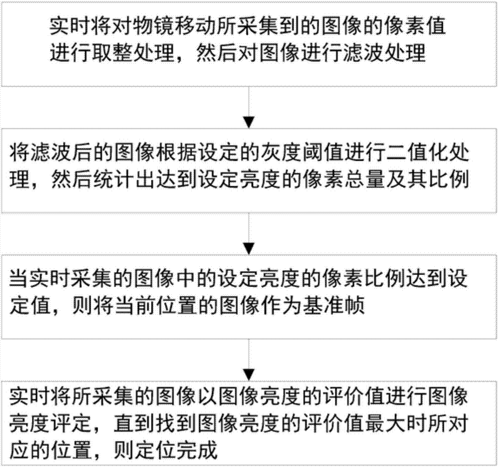
[0046] Such as figure 1 As shown, the invention provides a kind of objective lens positioning method based on light intensity, it is characterized in that, the method comprises following processing steps:

[0047] Step 1: In real time, the pixel value of the image collected by the movement of the objective lens is rounded up, and then the image is filtered;

[0048] Step 2: Binarize the filtered image according to the set gray threshold, and then count the total number of pixels reaching the set brightness and their proportion;

[0049] Step 3: When the pixel ratio of the set brightness in the real-time collected image reaches the set value, the image at the current positio...


PUM


Abstract

The present invention discloses a light intensity-based objective lens positioning method. The method comprises the following processing steps of 1 rounding the pixel values of an image acquired by the movement of an objective lens real-timely, and then filtering the image; 2 carrying out the binarization processing on the filtered image according to a set gray threshold, and then gathering the total number and the proportion of the pixels reaching the set brightness; 3 when the proportion of the pixels reaching the set brightness in the real-timely acquired image reaches a set value, taking the image at the current position as a reference frame; 4 real-timely carrying out the image brightness evaluation on the acquired image with the image brightness evaluation values until the position corresponding to the largest image brightness evaluation value is found, thereby finishing the positioning. According to the present invention, by evaluating the image energy, the deviation degree of the objective lens is determined, so that the center of an optical axis is searched, and accordingly, the positioning precision can be improved effectively, and the robustness is improved.

Description

technical field [0001] The invention relates to the field of optics, in particular to an objective lens positioning method based on light intensity. Background technique [0002] Since the imaging quality of a fully automatic microscope is closely related to the luminous flux of the optical path, and the luminous flux is affected by the degree of deviation of the objective lens from the optical axis, and because the light flux of the optical path will decrease with the increase of the deviation of the optical axis of the objective lens, the imaging quality will also increase. Therefore, the positioning and correction of the objective lens are the prerequisites for automatic focusing and clear imaging. Usually, a marker is used to mark the objective lens, and then the sensor detects the marker for positioning and correction. However, these sensing circuit-based assays not only increase mechanical complexity, but also introduce errors from the sensors themselves. [0003] Ac...

Claims


Application Information

Patent Timeline
Patent Type & Authority Applications(China)
IPC IPC(8): G06T7/00
CPCG06T7/0006G06T2207/20032
Inventor 玉振明彭国晋韦衡冰黄永庆周信健彭金虎黄腾
Owner WUZHOU UNIV
Learn More