Permanent magnet synchronous motor torque compensation method and permanent magnet synchronous motor compensation device

A permanent magnet synchronous motor, torque compensation technology, applied in the direction of control of electromechanical transmission, control of generators, motor-generator control, etc., can solve problems such as complex solutions, and achieve the effect of reducing complexity, simple engineering, and easy implementation

Inactive Publication Date: 2017-07-28
ZHUHAI GREE REFRIGERATION TECH CENT OF ENERGY SAVING & ENVIRONMENTAL PROTECTION
View PDF4 Cites 7 Cited by
  • Summary
  • Abstract
  • Description
  • Claims
  • Application Information

AI Technical Summary

Problems solved by technology

[0006] The invention provides a permanent magnet synchronous motor torque compensation method and a permanent magnet synchronous motor compensation device to at least solve the problem of suppressing the air gap magnetic field of a permanent magnet synchronous motor with different degrees of harmonics in the prior art. complicated question

Method used


Image

  • Permanent magnet synchronous motor torque compensation method and permanent magnet synchronous motor compensation device
  • Permanent magnet synchronous motor torque compensation method and permanent magnet synchronous motor compensation device
  • Permanent magnet synchronous motor torque compensation method and permanent magnet synchronous motor compensation device

Examples


Embodiment 1

[0056] The torque compensation method of the permanent magnet synchronous motor provided by the present invention will be described below with reference to the accompanying drawings.

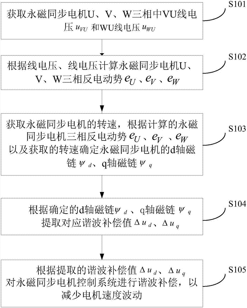
[0057] The permanent magnet synchronous motor torque compensation method provided by the present invention can be applied in the permanent magnet synchronous motor torque compensation control system, and can be realized by a hardware device that can realize its function, for example: the permanent magnet synchronous motor provided in this application In the magnetic synchronous motor compensation device, at the same time, the above method can also be written into one or more programs and stored on a computer-readable storage medium, and the one or more programs can be executed by one or more processors. figure 1 An optional flowchart showing the above method, as figure 1 As shown, the permanent magnet synchronous motor torque compensation method may include the following steps:

[0058] S101, o...

Embodiment 2

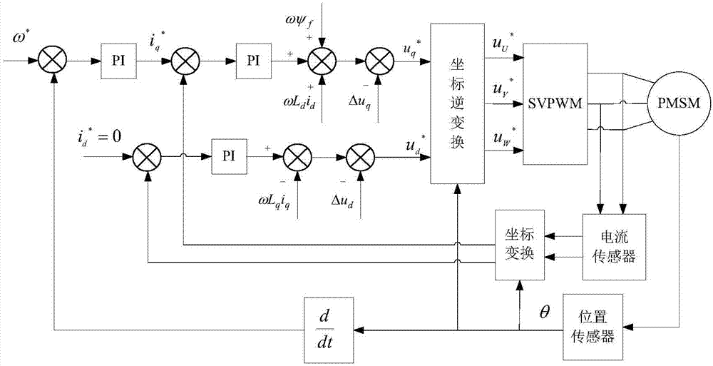
[0092] Based on the permanent magnet synchronous motor torque compensation method provided in the above embodiment 1, the optional embodiment 2 of the present invention also provides a permanent magnet synchronous motor compensation device, specifically, Figure 5 shows an optional structural block diagram of the device, such as Figure 5 As shown, the device includes:


PUM


Abstract

The invention discloses a permanent magnet synchronous motor torque compensation method and a permanent magnet synchronous motor compensation device. The method comprises the following steps of acquiring a permanent magnet synchronous motor line voltage uVU and a line voltage uWU; according to the line voltage uVU and the line voltage uWU, calculating a permanent-magnet synchronous-motor three-phase counter electromotive force; acquiring a rotation speed of the permanent magnet synchronous motor, and according to the calculated permanent-magnet synchronous-motor three-phase counter electromotive force and the acquired rotation speed, determining a d-shaft flux linkage psid and a q-shaft flux linkage psiq of the permanent magnet synchronous motor; according to the determined d-shaft flux linkage psid and the q-shaft flux linkage psiq, extracting corresponding harmonic wave compensation values delta ud and delta uq; and according to the extracted harmonic wave compensation values delta ud and delta uq, carrying out harmonic wave compensation on a permanent magnet synchronous motor control system so as to reduce a speed fluctuation. In the prior art, in a process that an air-gap magnetic field restraining the permanent magnet synchronous motor is with different degrees of harmonic waves, a scheme is complex. By using the method and the device of the invention, the above problem is solved and complexity of permanent magnet synchronous motor compensation control is reduced.

Description

technical field [0001] The invention relates to the technical field of motors, in particular to a torque compensation method for a permanent magnet synchronous motor and a compensation device for a permanent magnet synchronous motor. Background technique [0002] The permanent magnet synchronous motor has the advantages of simple structure, small size, high efficiency, reliable operation, wide speed range, good dynamic and static characteristics, etc., and is widely used in AC transmission systems. When the permanent magnet synchronous motor is working, whether the electromagnetic torque is stable is the key factor to measure the performance of the motor. The torque ripple will cause vibration and noise, increase the mechanical wear of the motor, and limit its application in high-precision occasions. The pulsation of the torque will cause the pulsation of the speed, which will reduce the precision of the motor speed control. [0003] The existence of harmonics in the air-ga...

Claims


Application Information

Patent Timeline
Patent Type & Authority Applications(China)
IPC IPC(8): H02P21/05
Inventor 刘玲曹巍王长恺张东盛区均灌程海珍徐常升于波
Owner ZHUHAI GREE REFRIGERATION TECH CENT OF ENERGY SAVING & ENVIRONMENTAL PROTECTION
Why Eureka
Try Eureka