Metal board positioning assembly

A technology of sheet metal and positioning components, applied in positioning devices, metal processing equipment, feeding devices, etc., can solve problems such as high cost, inability to adapt, and affect production efficiency, and achieve high automation efficiency and precise positioning.

Inactive Publication Date: 2017-08-01
王宝勤
View PDF1 Cites 0 Cited by
  • Summary
  • Abstract
  • Description
  • Claims
  • Application Information

AI Technical Summary

Problems solved by technology

[0003] 1. It must rely on the right-angled edge for positioning. If the sheet metal part is a material of any shape, stable positioning cannot be achieved;
[0004] 2. When the size and shape of sheet metal parts change, the positioning device must be readjusted and set, which leads to the automatic production line must be shut down when processing different parts, seriously affecting production efficiency
[0005] The Publication No. CN104942172A published by the State Intellectual Property Office on 2

Method used


Image

  • Metal board positioning assembly
  • Metal board positioning assembly
  • Metal board positioning assembly

Examples


Embodiment Construction

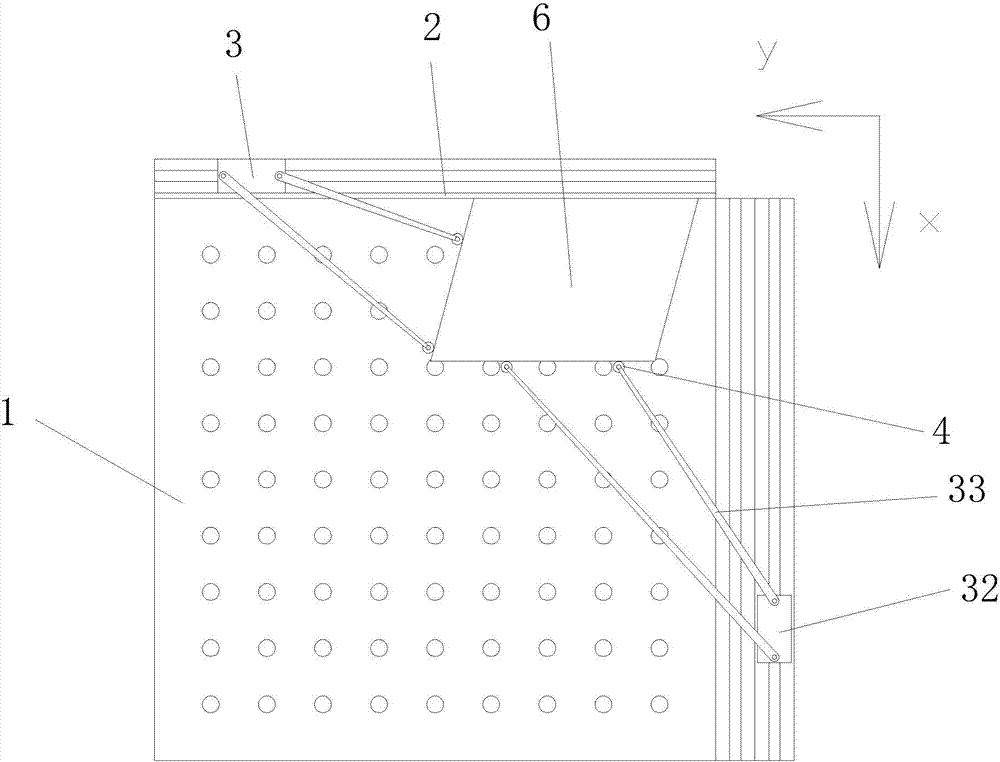
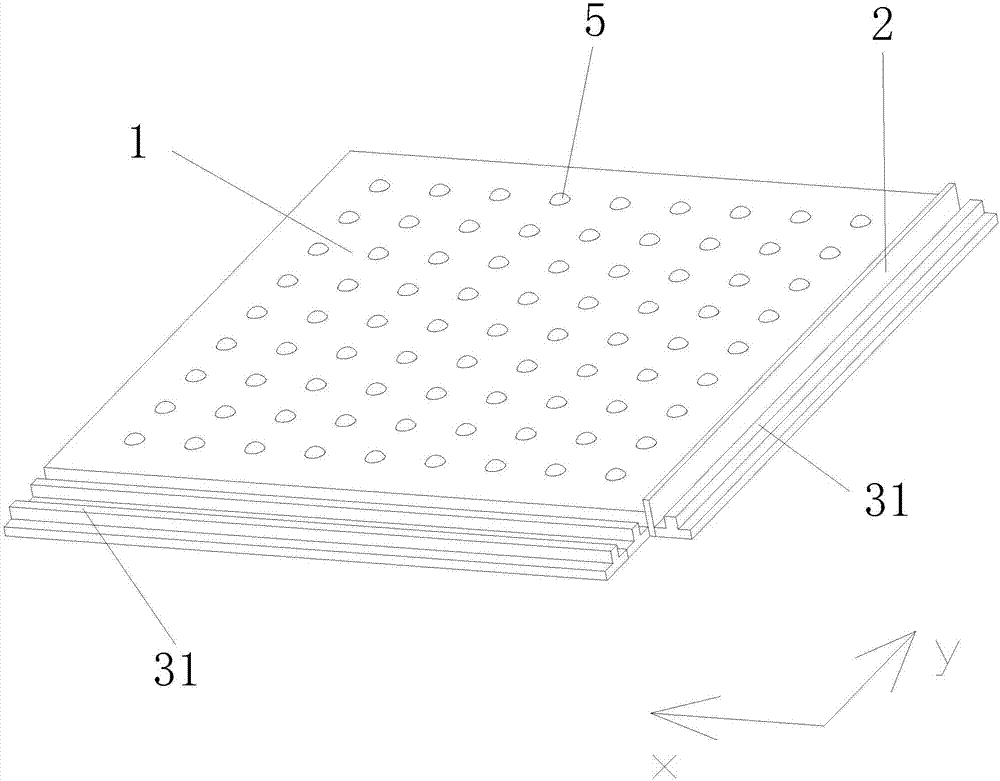
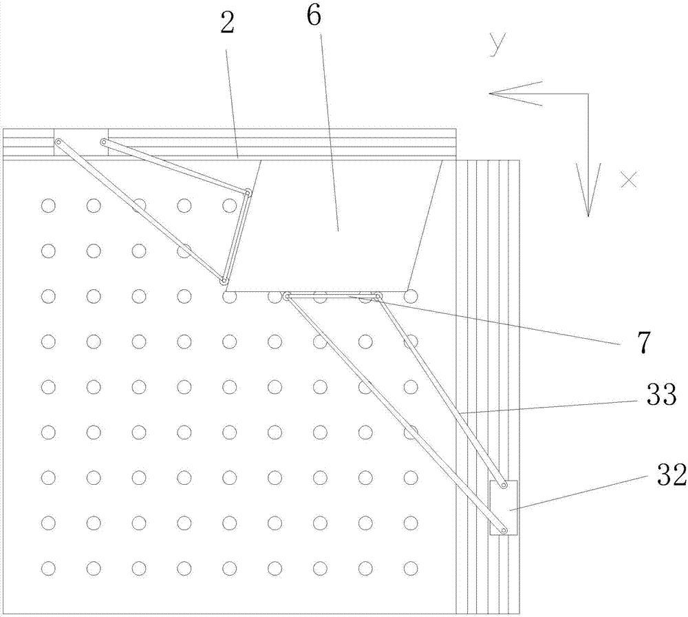
[0019] The present invention as Figure 1-3 As shown, it includes a workbench 1, a positioning rib 2 and a pair of positioning mechanisms 3. A pair of positioning mechanisms 3 are respectively arranged on both sides of the workbench at right angles, and form the X-direction and Y-direction positioning of the metal sheet 6,

[0020] The positioning rib 2 is perpendicular to the workbench and arranged along the right-angled side of the positioning mechanism in the Y direction on the workbench, and the positioning rib is located on the inside of the positioning mechanism in the Y direction;

[0021] Described positioning mechanism comprises guide rail 31, drive block 32 and a pair of electric push rod 33, and described drive block 32 is slidably connected on the described guide rail 31, and one end of a pair of electric push rod 33 is hinged on described drive block 32, The other end is hingedly provided with roller 4.

[0022] The positioning mechanism slides through the drivin...


PUM


Abstract

The invention discloses a metal board positioning assembly, and relates to a metal board automatic machining production line, in particular to a metal board automatic positioning assembly. The metal board positioning assembly is simple in structure, and capable of improving positioning adaptation and reliability. A positioning blocking side is perpendicular to a work table and is arranged along the right-angle side of a positioning mechanism in the Y direction of the work table, and the positioning blocking side is located on the inner side of the positioning mechanism in the Y direction; the positioning mechanism comprises a guide rail, a drive block and a pair of electric push rods, the drive block is in sliding connection to the guide rail, one ends of the electric push rods are hinge to the drive block, and the other ends of the electric push rods are provided with rollers in a hinged manner; a telescopic rod is arranged between the rollers on the electric push rods, and a plurality of rolling steel balls are evenly distributed on the top face of the work table. According to the assembly, precise positioning of irregular parts can be achieved, the assembly can automatically adapt to changes of the shape and the size of different parts, the automation efficiency is high, and the clamping phenomenon cannot appear.

Description

technical field [0001] The invention relates to an automatic processing production line for sheet metal, in particular to an automatic positioning assembly for sheet metal. Background technique [0002] Sheet metal parts must be precisely positioned before punching, laser cutting, and bending. The prior art mainly has the following problems: [0003] 1. It must rely on the right-angled edge for positioning. If the sheet metal part is a material of any shape, stable positioning cannot be achieved; [0004] 2. When the size and shape of sheet metal parts change, the positioning device must be readjusted and set, which leads to the automatic production line must be shut down when processing different parts, seriously affecting production efficiency. [0005] The Publication No. CN104942172A published by the State Intellectual Property Office on 2015.09.30 is a patent titled "A Plate Positioning System". When it is working, when the induction switches A and B have signals, the...

Claims


Application Information

Patent Timeline
IPC IPC(8): B23K26/70B21D43/00
CPCB23K26/702B21D43/003
Inventor 王宝勤
Owner 王宝勤
Why Eureka
Try Eureka