Air conditioning device for vehicle

一种空调装置、车辆的技术,应用在车辆部件、运输和包装、空气处理设备等方向,能够解决损害空气温度控制性、损害碰撞安全性、损害乘员空调舒适性等问题,达到提高空气温度控制性、提高碰撞安全性的效果

Inactive Publication Date: 2017-08-01
DENSO CORP
View PDF6 Cites 4 Cited by
  • Summary
  • Abstract
  • Description
  • Claims
  • Application Information

AI Technical Summary

Problems solved by technology

[0010] However, according to the research of the inventors of the present invention, in the above-mentioned prior art, there is a concern that the refrigerant / coolant heat exchanger is arranged in the engine room, which may impair the safety of the collision.
That is, since the refrigerant / coolant heat exchanger reduces the buffer space of the engine compartment (the space that is squeezed in the event of a vehicle collision), there is a possibility that the passenger compartment will be compressed in the event of a vehicle collision
[0011] In addition, in the above-mentioned conventional technology, the refrigerant in the refrigeration cycle cools and heats the air through the coolant, which may impair the air temperature controllability.
That is, since the coolant has a large heat capacity, it takes time to change the coolant and the air to the target temperature, which may impair the air-conditioning comfort of the occupants.

Method used


Image

  • Air conditioning device for vehicle
  • Air conditioning device for vehicle
  • Air conditioning device for vehicle

Examples


no. 1 approach

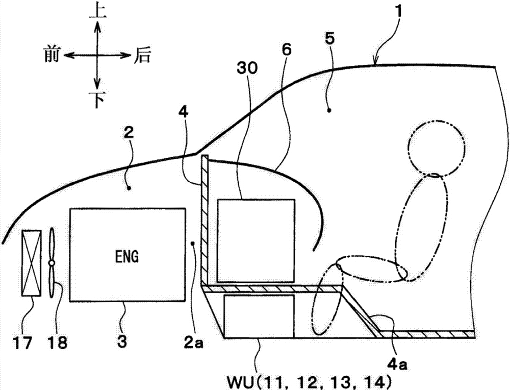
[0033] Below, based on Figure 1 to Figure 7 The first embodiment will be described. Up, down, front, back, left, and right arrows in the figure indicate the up, down, front, back, left, and right directions of the vehicle.

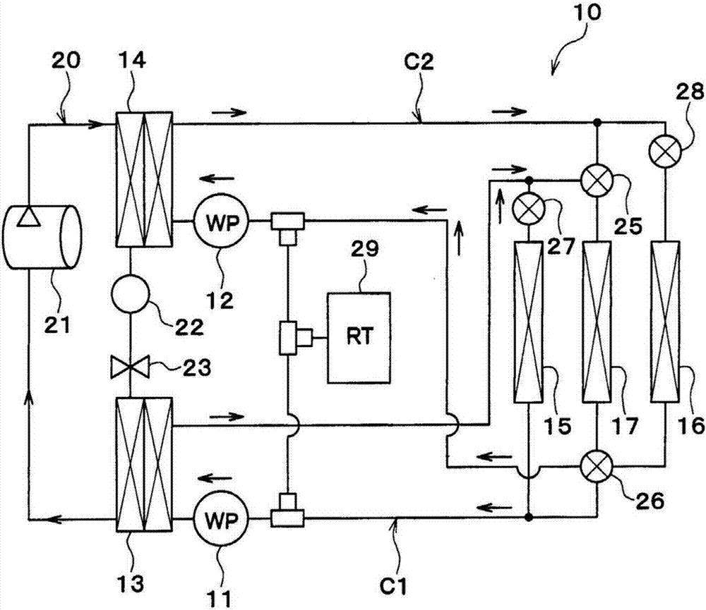
[0034] figure 1 The illustrated vehicle air conditioner 10 has a first pump 11 , a second pump 12 , a cooler 13 , a condenser 14 , a cooler core 15 , a heater core 16 , and a radiator 17 .

[0035] The first pump 11 and the second pump 12 are electric pumps that suck in and discharge cooling water (heat medium). Cooling water is a fluid as a heat medium. In this embodiment, a liquid containing at least ethylene glycol, dimethylpolysiloxane, or nanofluid or an antifreeze liquid can be used as the cooling water.

[0036] The cooler 13 , the condenser 14 , the cooler core 15 , the heater core 16 , and the radiator 17 are cooling water circulation facilities (heat medium circulation facilities) through which cooling water flows.

[0037] The cooler 13 an...

no. 2 approach

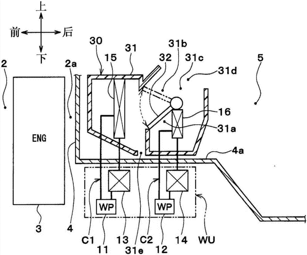
[0088] In this embodiment, if Figure 8 , Figure 9 As shown, the condensed water discharged from the condensed water discharge port 31 e of the housing 31 is guided to the condenser 14 . Figure 8 , Figure 9 The thick arrows schematically represent condensate flow.

[0089]Specifically, one end of a drain pipe (not shown) is connected to the condensed water discharge port 31e of the casing 31 , and the other end of the drain pipe is connected to the condenser 14 . The condensed water guided to the condenser 14 by the drain pipe flows inside or on the surface of the condenser 14 . Thereby, at least one of the refrigerant and the cooling water flowing inside the condenser 14 is cooled by the condensed water guided to the condenser 14 .

[0090] In the present embodiment, the condenser 14 is arranged at a position where condensed water generated in the casing 31 falls due to gravity. Thereby, the refrigerant cooling capability of the condenser 14 can be improved by using c...

no. 3 approach

[0092] In the above-mentioned second embodiment, at least one of the refrigerant and the cooling water flowing inside the condenser 14 is cooled by the condensed water from the condensed water discharge port 31e. The condensed water discharged from the outlet 31e cools the high-pressure side refrigerant of the refrigeration cycle 20 or the cooling water of the second cooling water circuit C2.

[0093] Specifically, as Figure 10 As shown, the pipe 41 is in contact with the drain pipe 40 so as to enable heat conduction. The high-pressure side refrigerant of the refrigeration cycle 20 or the cooling water of the second cooling water circuit C2 flows through the piping 41 .

[0094] The drain pipe 40 and the piping 41 are condensate-refrigerant heat exchange parts for exchanging heat between the condensate generated in the housing 31 and the refrigerant, or are used to exchange heat between the condensate generated in the housing 31 and cooling water (heat medium). ) The conden...


PUM


Abstract

An air conditioning device for a vehicle is provided with: first heat exchangers (13, 14) via which heat is exchanged between a heat medium and a refrigerant in a refrigeration cycle (20); second heat exchangers (15, 16) via which heat is exchanged between the heat medium and air blown into a vehicle cabin interior space (5); and a casing (31) disposed in the vehicle cabin interior space (5) and forming an air passage channeling air, the casing (31) accommodating the second heat exchangers (15, 16). The first heat exchangers (13, 14) are disposed on the lower side of the casing (31). A partition (4) partitioning the vehicle cabin interior space (5) and an engine compartment (2) is interposed between the first heat exchangers (13, 14) and the casing (31).

Description

[0001] Cross-reference of related applications [0002] This application is based on Japanese Patent Application No. 2014-249628 for which it applied on December 10, 2014, The disclosure content is taken in this application by reference. technical field [0003] The invention relates to an air conditioning device for a vehicle. Background technique [0004] Conventionally, Patent Document 1 describes a cooling and heating device for an automobile, which has a refrigerant / cooling system that cools and heats the coolant by exchanging heat between the refrigerant and the coolant in the refrigeration cycle. a coolant heat exchanger; and a coolant / air heat exchanger that cools and heats the air by exchanging heat between the coolant and the air. [0005] In this prior art, the refrigerant in the refrigeration cycle cools and heats the air through the coolant, thereby cooling and heating the cabin. [0006] In this prior art, the refrigerant / coolant heat exchanger is arranged in...

Claims


Application Information

Patent Timeline
Patent Type & Authority Applications(China)
IPC IPC(8): B60H1/00B60H1/03B60H1/32
CPCB60H1/00521B60H1/32284B60H1/32331B60H1/00B60H1/32B60H1/00514
Inventor 大见康光
Owner DENSO CORP
Why Eureka
Try Eureka