Cut-off mechanism including a strip actuated by an electromagnet comprising two air-gaps

An electromagnet and air gap technology, which is applied in the field of motor vehicle headlights and lighting headlights, can solve the problems of large electromagnets, expensive, undesired price and size, and achieve the effect of size reduction

Active Publication Date: 2017-08-01
AML SYST
View PDF3 Cites 2 Cited by
  • Summary
  • Abstract
  • Description
  • Claims
  • Application Information

AI Technical Summary

Problems solved by technology

These solutions have the disadvantage of being relatively expensive (in the case of copper) or requiring larger electromagnets, which is undesirable for the price as well as for its size

Method used


Image

  • Cut-off mechanism including a strip actuated by an electromagnet comprising two air-gaps
  • Cut-off mechanism including a strip actuated by an electromagnet comprising two air-gaps
  • Cut-off mechanism including a strip actuated by an electromagnet comprising two air-gaps

Examples


Embodiment Construction

[0027] In the following description, references to the optical axis of the mirror include longitudinal or lateral references, and the terms front or rear refer to the direction of beam propagation.

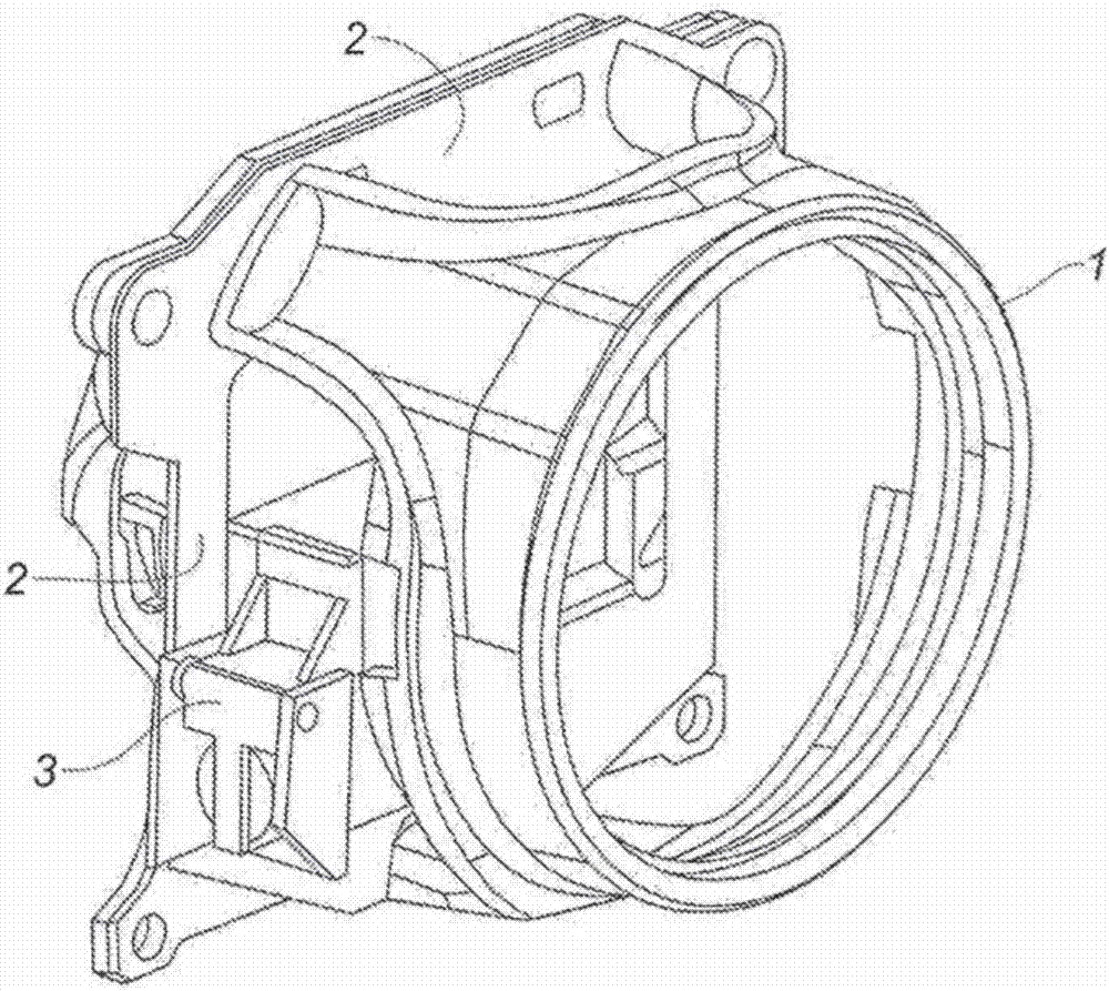
[0028] refer to figure 1 , the front part of a motor vehicle headlamp can be seen, which comprises a cylindrical lens holder 1 extending from a rectangular frame 2 towards the front. A rectangular frame extends into a plane perpendicular to the optical axis of the beam and is cut in its center to pass said beam. A cut-off mechanism is fixed on the frame, and the function of the cut-off mechanism is to block the light beam more or less according to the driving conditions of the vehicle. Invisibly, the light source generating the light beam and the mirrors directing the light beam towards the front and towards the lens (not shown) are positioned behind the frame mounted on the front edge of the lens holder 1 .

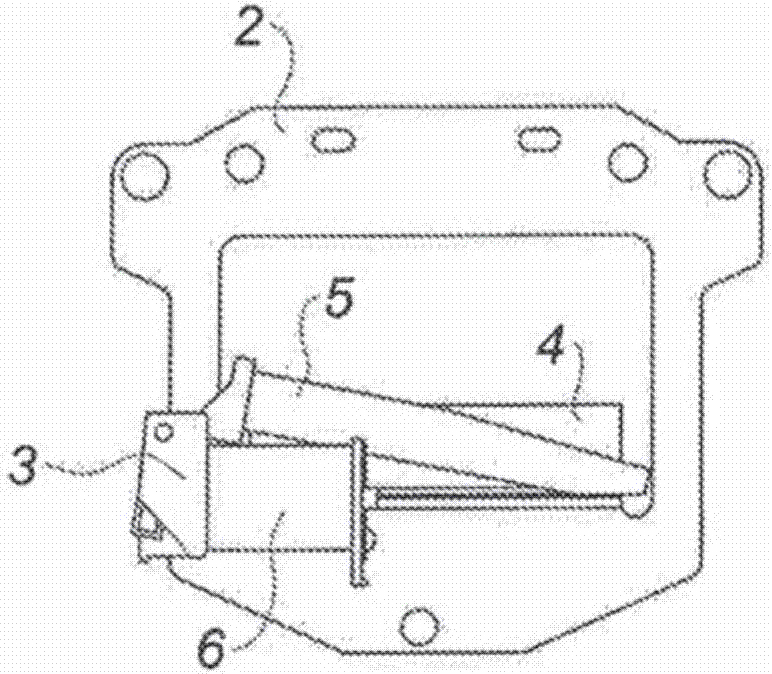
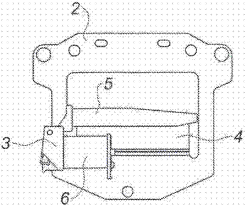
[0029] refer to figure 2 and image 3 , the front view of the shut...


PUM


Abstract

Cut-off mechanism for an automotive vehicle headlamp comprising a strip (5) borne by a movable assembly (40) and shaped to block to a greater or lesser extent a light beam so as to change the optical operating mode of said headlamp, said mechanism furthermore comprising a motor (6) for actuating said movable assembly using an electromagnet including an inductive coil (61) associated with a fixed ferromagnetic core (62) positioned in its centre and with a metal carcass (64) surrounding said coil, said movable assembly being movable under the action of said electromagnet, against the action of a return spring, between a contact position and a distant position, via a first air-gap (h1) of said ferromagnetic core (62). Said movable assembly (40) is shaped to create a rupture in the continuity of the magnetic circuit formed by said ferromagnetic core (62), said metal carcass (64) and said movable assembly (40), when it makes contact with said ferromagnetic core (62).

Description

technical field [0001] The field of the invention is that of illuminated headlamps, more particularly of headlamps for motor vehicles. Background technique [0002] Motor vehicle headlamps generally comprise a reflector in which a light source and means for controlling the shape of the light beam are positioned in order to adapt the reflector to the driving situation. [0003] It is known to employ cut-off bands capable of blocking the beam at various stages. The belt is electrically actuated on command to move it between at least two angular positions, wherein the belt more or less blocks the light beam. This makes it possible to limit the range of the headlights to, for example, low beam headlights, known as the low beam position, without blinding drivers traveling in the opposite direction, or to what is known as the road position, The range of main beam headlamps in which there is no obscuration. [0004] Prior art means for controlling the belt position generally con...

Claims


Application Information

Patent Timeline
IPC IPC(8): F21S8/12F21S8/10F21V11/18F21V14/08F21V5/04F21W101/10
CPCF21S41/686F21V5/04F21V11/183F21W2102/00
Inventor 丹尼尔·洛佩斯哈桑·寇劳
Owner AML SYST
Why Eureka
Try Eureka