Outdoor unit
A technology of outdoor units and indoor units, applied in the field of outdoor units, can solve the problems of difficult outdoor units and configuration outside the house, and achieve the effect of suppressing large-scale
- Summary
- Abstract
- Description
- Claims
- Application Information
AI Technical Summary
Problems solved by technology
Method used
Image

Examples
Embodiment approach
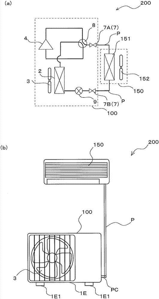
[0026] figure 1 It is a schematic diagram of the air conditioner 200 provided with the outdoor unit 100 of this embodiment. figure 1 (a) shows an example of the refrigerant circuit configuration of the air conditioner 200, in figure 1 (b) shows the state where the outdoor unit 100 and the indoor unit 150 are connected by the refrigerant pipe P. As shown in FIG. In addition, in this embodiment, an example in which the refrigeration cycle device is the air conditioner 200 will be described.
[0027] About air conditioner 200
[0028] The air conditioner 200 is configured by including an indoor unit 150 and an outdoor unit 100 , and these are connected by refrigerant piping P. As shown in FIG. The indoor unit 150 has an indoor heat exchanger 151 and the like which function as an evaporator during cooling operation and as a condenser during heating operation. Then, the low-temperature energy or high-temperature energy generated by the outdoor unit 100 is delivered to the indoo...
Deformed example 1
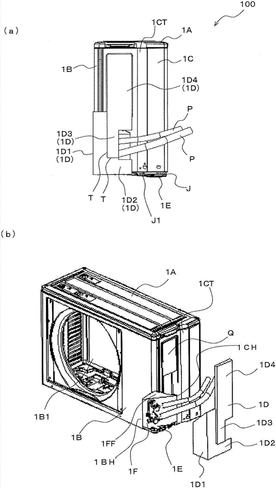
[0085] Figure 6 This is Modification 1 of the outdoor unit 100 of this embodiment. Figure 6 (a) is a perspective view of the outdoor unit 100, Figure 6 (b) is a front view of the outdoor unit 100 . In this embodiment, in order to expand the capacity of the machine room R1, the front end (the vertex when the angle is at a right angle) of the roof panel 1FF is located on the front side, and the vertex of the corner C is located below the vertex with the largest angle. .
[0086] On the other hand, in Modification 1, the position of the vertex of the right angle of the roof panel 1FF is located on the back side. Therefore, the bent portion 21 is formed on the front panel 1B, and the bent portion 22 is formed on the second side panel 1C. The front panel 1B and the second side panel 1C are arranged along the end of the bent portion 21 and the end of the bent portion 22 .
[0087] In addition, in Modification 1, the fixed panel 1F, the cover 1D, and the second side panel 1C ...
Deformed example 2~6
[0091] Figure 7A ~ Figure 7E These are modification examples 2 to 6 of the outdoor unit according to the embodiment of the present invention. In Modification 2 to Modification 6 below, various modifications of the bottom panel 1E are shown. In addition, the second side panel 1C is formed along the peripheral edge portion 1E1 of the bottom panel 1E.
[0092] The difference between the embodiment of the outdoor unit 100 of this embodiment and the embodiments of the outdoor unit 100 of Modification 2 to Modification 6 will be described.
[0093] In Modification 2 to Modification 6, the fixed panel 1F disposed inside the peripheral edge portion 1E1 of the bottom panel 1E is not provided.
[0094] In addition, in Modification 2 to Modification 6, the valve 7 is attached to the second side panel 1C.
[0095] In addition, in the present embodiment and Modification 1, the surface of the cover 1D is along the surface of the second side panel 1C, but in Modifications 2 to 6, the cov...
PUM
 Abstract
Description
Claims
Application Information
 - R&D Engineer
- R&D Manager
- IP Professional
- Industry Leading Data Capabilities
- Powerful AI technology
- Patent DNA Extraction
Browse by: Latest US Patents, China's latest patents, Technical Efficacy Thesaurus, Application Domain, Technology Topic.
© 2024 PatSnap. All rights reserved.Legal|Privacy policy|Modern Slavery Act Transparency Statement|Sitemap