
Method and apparatus for operating a resolver, and resolver device

A resolver and equipment technology, which is applied in the field of equipment operating the resolver, and can solve the problems of confusing excitation winding joints and the like

Active Publication Date: 2017-08-01
ROBERT BOSCH GMBH
View PDF7 Cites 0 Cited by
  • Summary
  • Abstract
  • Description
  • Claims
  • Application Information

AI Technical Summary

Problems solved by technology

If the resolver is coupled or connected upside down, thereby confusing the connections of the field windings, this leads to an inversion of the detected position information

Method used


Image

  • Method and apparatus for operating a resolver, and resolver device
  • Method and apparatus for operating a resolver, and resolver device
  • Method and apparatus for operating a resolver, and resolver device

Examples


Embodiment Construction

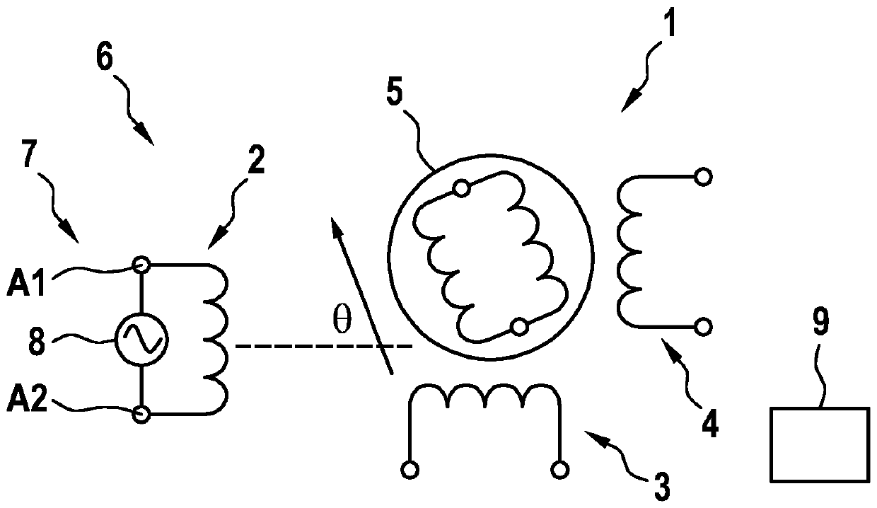
[0018] figure 1 A conventional resolver 1 with a field winding 2 and a first receiving winding 3 and a second receiving winding 4 is shown in a simplified illustration. The receiving windings 3 and 4 are arranged circumferentially offset from one another by 90° around a shaft 5 , for example the rotor shaft of an electric machine. The shaft 5 is rotatably mounted and can carry the field winding 2 , wherein the field winding 2 can then be electrically contacted, for example via slip rings or brushes. According to the current exemplary embodiment, however, it is provided that the field winding 2 is also assigned to the rotor in a fixed manner to the stator or to the housing in order to inductively couple the magnetic field into the rotor. It operates with an excitation signal of a given amplitude and frequency.

[0019] The shaft 5 is, for example, connected in a rotationally fixed manner to the output shaft of the electric machine, so that the angular position of the shaft 5 ...


PUM


Abstract

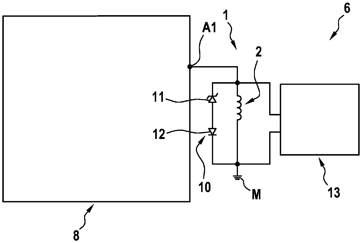
The invention relates to an apparatus (7) for operating a resolver (1), which has at least one receiver winding (3, 4) or at least one excitation winding (2), which are / can be associated with a rotatably mounted shaft (5), in particular a rotor shaft of an electric motor, said apparatus also having a device (9) which determines an angular position of the shaft (5) as a function of an induced voltage detected by the excitation winding (2) by means of a desired excitation signal (SES) with a predeterminable frequency and amplitude and by the receiver winding (3, 4). According to the invention, means (10) for limiting an electrical voltage on the excitation winding (2) are associated with the excitation winding (2), wherein the means (10) limit the voltage only above a maximum normal voltage in only one current direction.

Description

technical field [0001] The invention relates to a device and an arrangement for operating a resolver having at least one receiving winding and at least one field winding which are / can be assigned to A rotatably mounted shaft, in particular a rotor shaft of an electric motor; the device determines the angular position of the shaft as a function of the induced voltage, which is passed through the field winding by means of a predeterminable frequency and amplitude A desired excitation signal is generated and detected by the receiving winding, which can in particular be predetermined by the device. [0002] Furthermore, the invention relates to a method for operating such a resolver and to a resolver arrangement. Background technique [0003] In order to detect the angular position of the rotor of an electric machine, resolvers are also frequently used in the motor vehicle sector. The resolver is an electromagnetic measuring transducer which outputs an electrical variable, in ...

Claims


Application Information

Patent Timeline
Patent Type & Authority Applications(China)
IPC IPC(8): G01D5/20G01D18/00
CPCG01D5/2073G01D18/00
Inventor M.基尔施纳E.埃贝莱因
Owner ROBERT BOSCH GMBH
Learn More