Plasma torch equipped with waveguide in which swirl flow collapses gas supply part

A plasma and gas supply technology, applied in the direction of plasma, manufacture of combustible gas, electrical components, etc., can solve the problems of reduced production efficiency of synthetic gas and inability to flow in, and achieve the goals of increasing reaction time, easy application, and increasing manufacturing efficiency Effect

Inactive Publication Date: 2019-02-12
GREEN SCI CO LTD
View PDF7 Cites 0 Cited by
  • Summary
  • Abstract
  • Description
  • Claims
  • Application Information

AI Technical Summary

Problems solved by technology

[0004] However, although the existing plasma torch can stabilize the plasma through the vortex flow, the injected hydrocarbon cannot flow into the plasma due to the vortex flow.
[0005] As a result, the injected hydrocarbons cannot pass through the plasma accurately, resulting in a significant reduction in the production efficiency of the forming gas

Method used


Image

  • Plasma torch equipped with waveguide in which swirl flow collapses gas supply part
  • Plasma torch equipped with waveguide in which swirl flow collapses gas supply part
  • Plasma torch equipped with waveguide in which swirl flow collapses gas supply part

Examples


Embodiment Construction

[0041] Preferred embodiments of the present invention that can achieve the object of the present invention will be described below with reference to the drawings. In the description of the present embodiment, the same components are given the same names and the same reference numerals, and additional description thereof will be omitted.

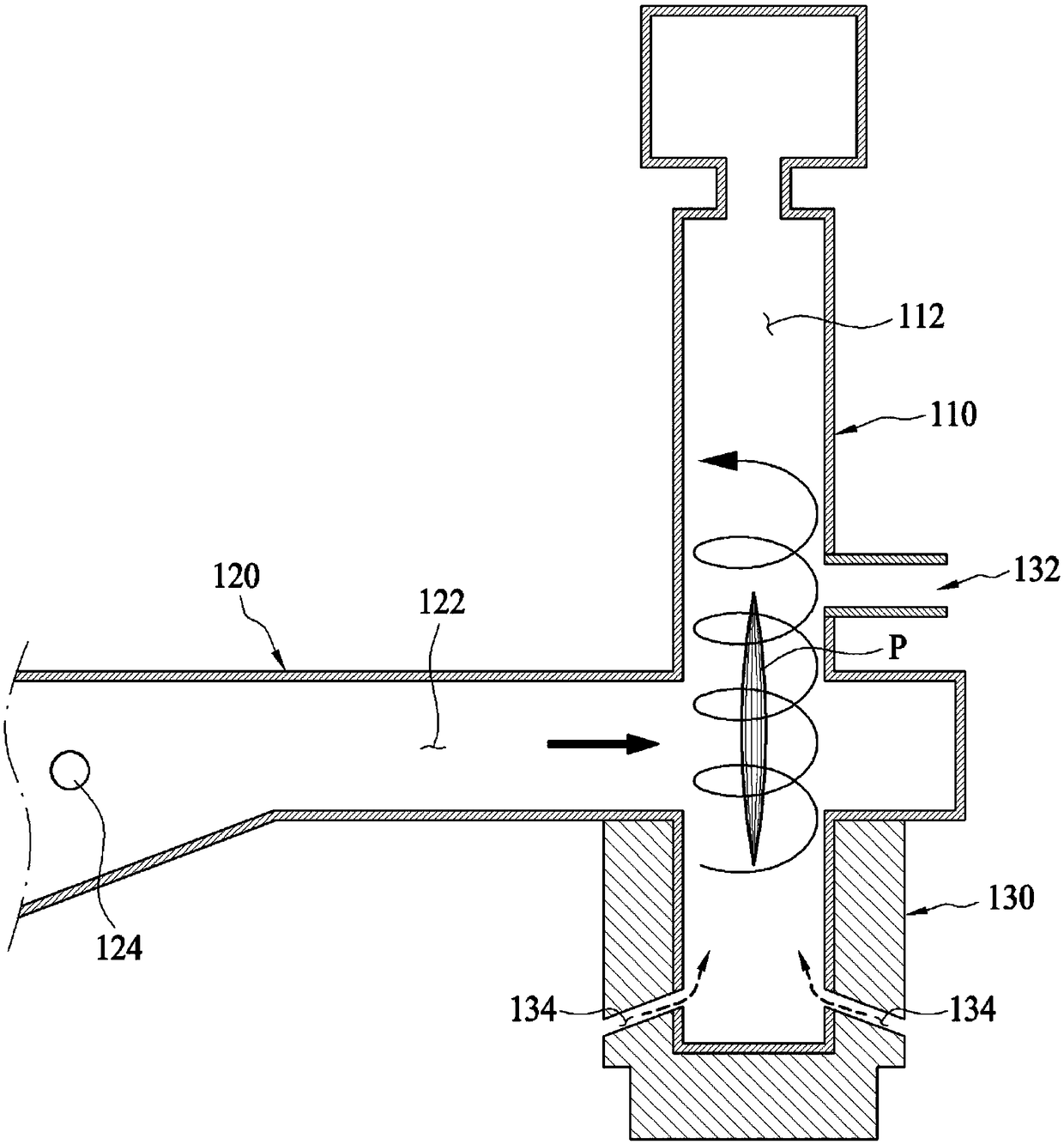
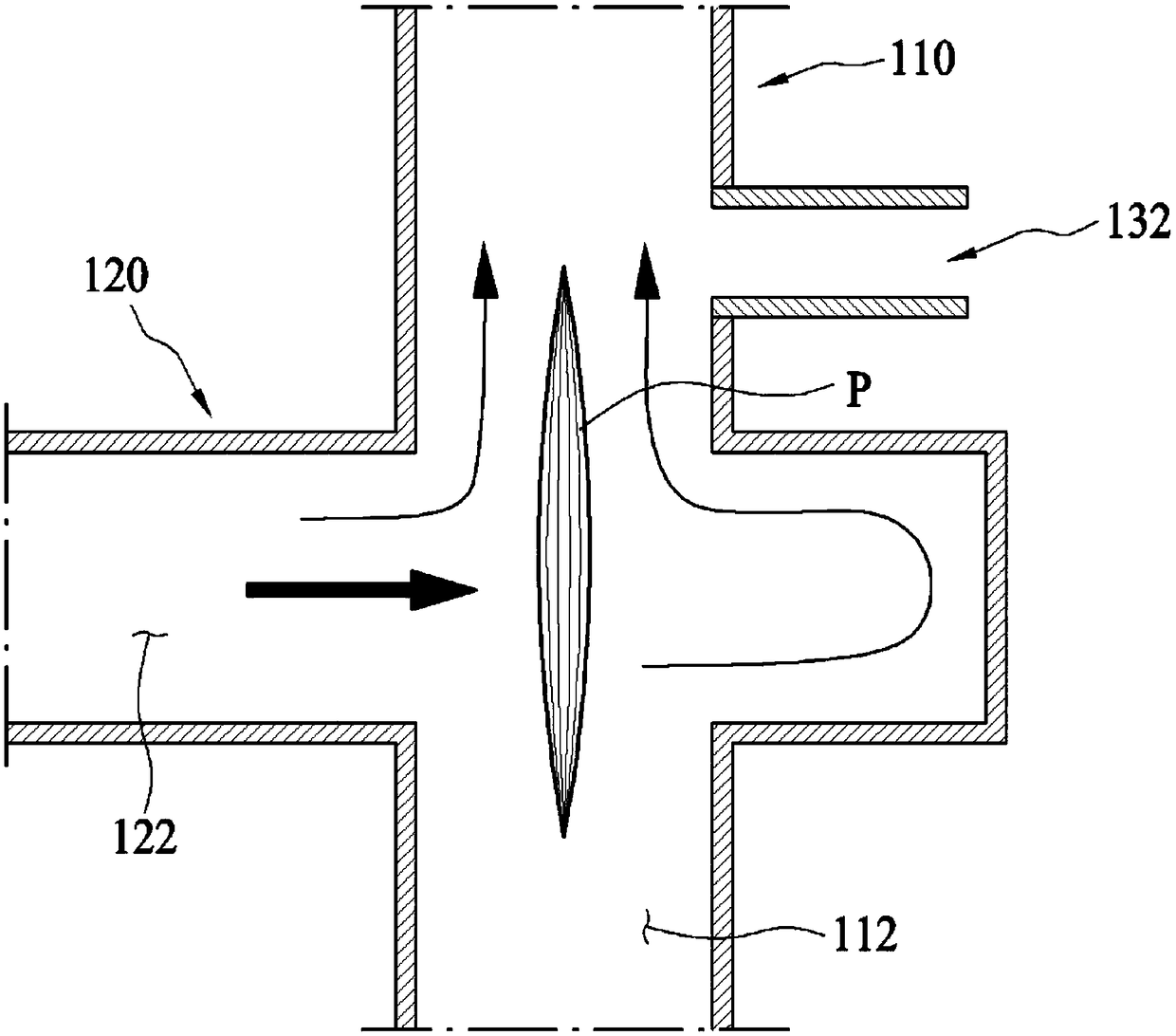
[0042] figure 1 is a sectional view showing the structure of the plasma torch according to the first embodiment of the present invention, figure 2 is a cross-sectional view showing a state where a swirl flow is injected through the waveguide 120 to disintegrate gas in the plasma torch according to the first embodiment of the present invention.

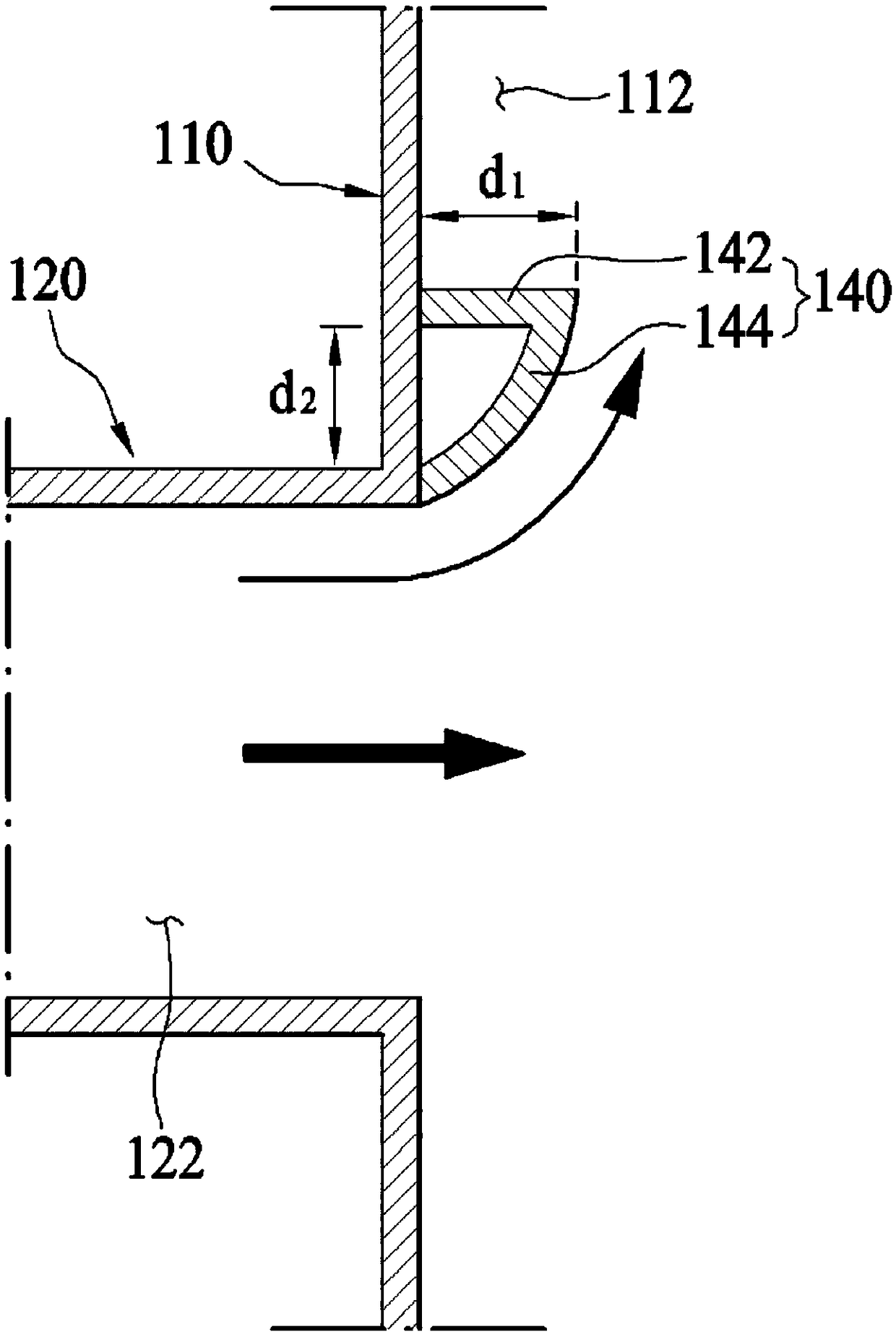
[0043] Such as Figure 1 to Figure 4 As shown, the plasma torch according to the first embodiment of the present invention includes a reactor 110 and a waveguide 120 .

[0044] The reactor 110 has a reaction space 112 formed therein, and includes a raw material injection part 114 and a swirl flow...


PUM


Abstract

A plasma torch of the present invention having a waveguide formed with a vortex air flow collapsing gas supply part includes a waveguide including a microwave irradiating part having an opening formed on one side thereof and irradiating microwaves toward the opening side to generate plasma that vaporizes hydrocarbons supplied into the swirl gas flow formed in front of the opening; and a swirl gas flow disintegrating gas supply portion that supplies a swirl gas flow that collapses a part of the swirl gas flow formed in front of the opening portion Disintegrate gas. Another aspect of the present invention is a plasma torch provided with a waveguide formed with a swirling gas flow collapsing gas supply part, including: a reactor in which a reaction space is formed and includes a raw material injection part for injecting hydrocarbons into the reaction space and a swirl flow generation gas supply part that supplies a swirl flow generation gas that generates a swirl flow to the reaction space; and a waveguide that is connected to the reactor and includes irradiating microwaves to generate gasified hydrocarbons within the swirl flow in the reaction space The microwave irradiating part of the plasma and the supply part of the vortex flow disintegrating gas that is part of the vortex gas flow formed in the reaction space are disintegrated by the vortex flow disintegration gas supply part.

Description

technical field [0001] The present invention relates to a plasma torch for gasifying hydrocarbons to generate synthesis gas, and more specifically, to a plasma torch provided with a swirl flow breaking gas supply unit for breaking a swirl flow formed in a reaction space. Plasma torch for stillpipe. Background technique [0002] Typically, plasma torches are utilized for fuelizing or using hydrocarbons produced from coal, biofuels, etc. to generate electricity. [0003] The plasma torch generates plasma using microwaves, supplies and gasifies hydrocarbons to the plasma to generate synthesis gas. At this time, it is necessary to stabilize the plasma generated during this process, and for this purpose, a predetermined gas for generating a swirl gas flow is injected into the reactor. A vortex flow generated by the injected gas flows along the periphery of the reactor, whereby the plasma is stabilized within the vortex flow. [0004] However, although the conventional plasma t...

Claims


Application Information

Patent Timeline
Patent Type & Authority Patents(China)
IPC IPC(8): H05H1/26C10J3/20
CPCC10J3/20H05H1/26C10J3/487C10J2300/0916C10J2300/093C10J2300/0943C10J2300/0956C10J2300/1238
Inventor 崔允硕玉昌宇姜炳善李学柱金浩俊
Owner GREEN SCI CO LTD
Why Eureka
Try Eureka