Processing device and method for wood processing

A technology for processing equipment and wood, which is applied in the direction of wood processing equipment, sawing equipment, manufacturing tools, etc. It can solve problems such as cracks, large stress area, damage, etc., and achieve smooth cutting, good consistency of cutting direction, and rough edges little effect

Pending Publication Date: 2017-08-04
东莞市野马精密机械有限公司
View PDF11 Cites 4 Cited by
  • Summary
  • Abstract
  • Description
  • Claims
  • Application Information

AI Technical Summary

Problems solved by technology

The tool requires a very large external force when cutting, and it is broken by pure mechanical force. Its fatal shortcoming is that it can only cut softer and smaller materials.
The second existing processing tool adopts a spiral trapezoidal knife. The knife rotates at a high speed, and the knife is driven by a motor to rotate. Its force-bearing area is relatively large, and too large force-bearing area leads to a large cutting force on complementary cutting products. , for products with too strong fibers or surface veneers, it is easy to cause cracks
[0003] At present, the density board is processed by trapezoidal knife and single saw blade. Due to the large contact surface of the trapezoidal knife, direct cutting will cause large-scale damage. The contact surface of the trapezoidal knife is more than 5 times that of the saw blade (the contact width of the saw blade is about 3MM)
[0004] At present, there are still applications of four-axis processing equipment in the market, but the saw blade is installed in the horizontal direction. A single saw blade is generally used for slotting and cannot be used as a tenon slot. When using a single cutting module, the cutting operation is in one direction. , there is no way for the two cutting edge outlets to be consistent

Method used


Image

  • Processing device and method for wood processing
  • Processing device and method for wood processing
  • Processing device and method for wood processing

Examples


Embodiment Construction

[0028] The present invention will be described in further detail below in conjunction with the accompanying drawings and specific embodiments.

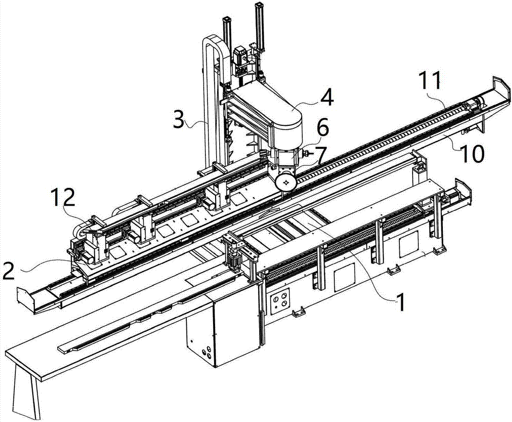
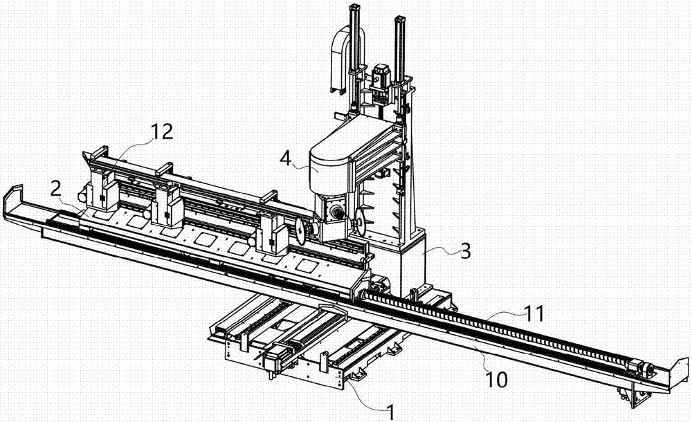
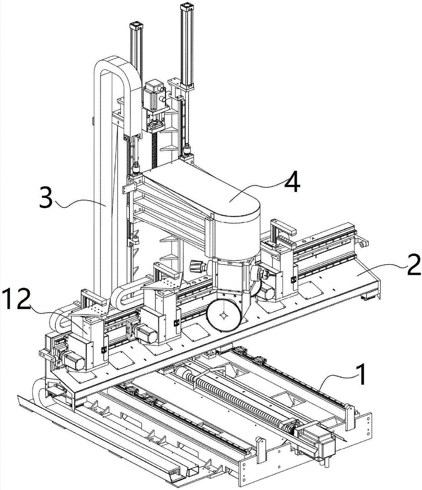
[0029] Such as Figure 1-5 As shown, the specific embodiment of the present invention is a kind of processing equipment for wood processing, including a machine base 1, a workbench 2 for fixing wood 15 is arranged above the machine base 1, and on the machine base 1 A vertical movable seat 3 is provided, and a processing box 4 is movable on the vertical movable seat 3, and the processing box 4 moves vertically up and down along the vertical movable seat 3;

[0030] The inner side of the processing box 4 is provided with a rotating motor 5, and the rotating motor 5 is driven and connected with a tenon knife driving module 6 and a saw blade driving module 7, and the two ends of the saw blade driving module 7 are respectively driven and connected with a vertically arranged first For the saw blade 8 and the second saw blade 9 , the rotati...


PUM


Abstract

The invention discloses a processing device and method for wood processing. A workbench used for fixing timbers is arranged on a machine base. A vertical movable base is arranged on the machine base. A processing tank body is movably arranged on the vertical movable base and vertically moves up and down along the vertical movable base. The processing device is provided with a rotary motor, automatic rotation of a tenon driving module and a sawblade driving module, the effect that the sawblade processing modes are changed according to different processing paths is achieved, in combination of switching of a tenon tool and a mortise tool, a horizontal movable base and a horizontal guide rail are arranged, and thus full-automatic processing operation can be achieved; bevel edges of mortises are subjected to cutting molding through sawblades, sawblade cutting is smooth, and burrs of cuts are few; and meanwhile, the left bevel edges of the mortises are cut through the first sawblade, the right bevel edges of the mortises are cut through the second sawblade, and the cutting direction consistency is better.

Description

technical field [0001] The invention relates to the field of wood processing equipment, in particular to a processing equipment and method for wood processing. Background technique [0002] Due to the needs of installation, the existing wood needs to be processed with a trapezoidal connection port with openings to facilitate installation and stability. In the existing processing tools, the shape of the first cutter is trapezoidal, the cutter does not rotate, and the power is manual or electric. The required external force is very large when the tool is cut, and it is broken by purely mechanical force. Its fatal shortcoming is that it can only cut softer and smaller materials. The second existing processing tool adopts a spiral trapezoidal knife, which rotates at a high speed and is driven by a motor to rotate. Its force-bearing area is relatively large, and too large force-bearing area leads to a great cutting force on complementary cutting products. , For products with to...

Claims


Application Information

Patent Timeline
IPC IPC(8): B27C9/04B27B5/02B27B5/18B27B5/29B27B25/00B27F5/02
CPCB27B5/02B27B5/187B27B5/29B27B25/00B27C9/04B27F5/02
Inventor 唐军
Owner 东莞市野马精密机械有限公司
Why Eureka
Try Eureka