
Anti-pollution window for heat evaporation coating instrument

A coating instrument and anti-pollution technology, which is applied in the field of anti-pollution windows, can solve problems such as hindering condensation, and achieve the effect of improving cleanliness and clarity

Active Publication Date: 2017-08-04
EAST CHINA NORMAL UNIV
View PDF10 Cites 3 Cited by
  • Summary
  • Abstract
  • Description
  • Claims
  • Application Information

AI Technical Summary

Problems solved by technology

[0003] The purpose of the present invention is to provide a kind of anti-pollution window for thermal evaporation coating instrument for the deficiencies in the prior art. The observation hole is divided into two sections, the cat's eye hole and the bell mouth, and the cat's eye is set in the cat eye hole; the cooling plate of the semiconductor refrigerator is set in the air duct, so that the temperature around the bell mouth is cooled, and the metal vapor condenses around the bell mouth, hindering It condenses on the curved mirror; set the rocker of the sweeping module in the sweeping rod cavity of the condensation cabin, and the brush on the rocker brushes the curved mirror of the cat's eye and the bell mouth port to remove a small amount of no Metal vapor condensed around the bell mouth and close to the curved mirror; the invention effectively improves the cleanliness and clarity of the window of the thermal evaporation coating instrument, enabling the experimenter to observe the melting of the metal in the evaporation container anytime, anywhere and for a long time. Control the optimal timing of opening the shutter to ensure high-quality coatings

Method used


Image

  • Anti-pollution window for heat evaporation coating instrument
  • Anti-pollution window for heat evaporation coating instrument

Examples


Embodiment

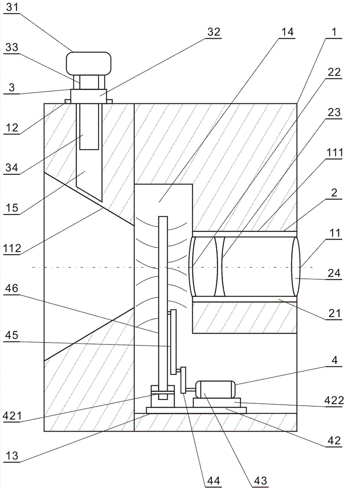
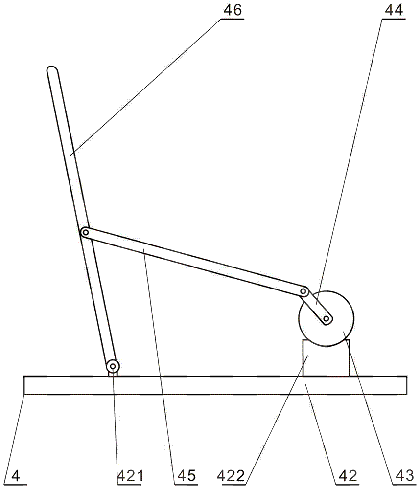
[0023] refer to figure 1 , figure 2 , the present invention provides an anti-pollution window for a thermal evaporation coating instrument, comprising a condensation chamber 1, a peephole 2, a semiconductor refrigerator 3 and a sweeping module 4. When in use, only the bell mouth 112 of the condensation chamber 1 and the The viewing port of the evaporating container can be aligned and installed. For ease of operation, the present invention provides a sweeping module 4 switch and a semiconductor refrigerator 3 switch outside the condensation chamber 1 for manipulation by experimenters. The rotation speed of the stepper motor 43 is controlled by the switch of the sweeping module 4 to control the stop, start and swing speed of the rocker 46;

[0024] refer to figure 1 , figure 2 , the present invention sets observation hole 11, refrigerator seat 12, sweeping module seat 13, sweeping rod cavity 14 and vertical air duct 15 in condensation chamber 1, and observation hole 11 is d...


PUM


Abstract

The invention discloses an anti-pollution window for a heat evaporation coating instrument. The anti-pollution window comprises a condensation bin, a peephole, a semiconductor cooler and a scanning module. A cooler seat, a scanning module seat, a scanning bar cavity and an air channel are arranged in the condensation bin. A cold conduction piece of the semiconductor cooler is arranged in the air channel, and therefore the periphery of a horn mouth is cooled, and metal steam is condensed on the periphery of the horn mouth and is stropped from being condensed on a curved mirror. An observation hole is divided into a peephole hole and the horn mouth, and the peephole is formed in the peephole hole. A rocking bar of the scanning module is arranged in the scanning bar cavity of the condensation bin, and a brush on the rocking bar is arranged on the curved mirror of the peephole and a horn end opening in a sweep-brushing manner so as to remove little metal steam which is not condensed on the periphery of the horn mouth and is close to the curved mirror. According to the anti-pollution window, the cleanliness and clearness of the window of the heat evaporation coating instrument are effectively improved, experimenters can observe the condition of metal melting in an evaporation container for a long time anytime and anywhere, the optimal time of opening a baffle can be controlled, and it can be ensured that high-quality coating is completed.

Description

technical field [0001] The invention relates to the technical field of thermal evaporation coating, which is used for observing the metal melting process in an evaporation container, in particular to an anti-pollution window for a thermal evaporation coating instrument. Background technique [0002] Thermal evaporation coating is used in a vacuum environment to melt the solid raw material to be formed in the evaporation container by electric heating, and its atoms or molecules gasify and escape from the surface to form a vapor flow, which is evaporated to the surface of the sample above the evaporation container , The technology of condensing to form a solid film is called thermal evaporation coating technology. Thermal evaporation coating technology is one of the oldest physical vapor deposition PVD technologies. It is mainly used to evaporate Ag, Al, Cu, Cr, Au, Ni, Cd, Pb and other metal materials. It can be widely used in universities, colleges, scientific research Scie...

Claims


Application Information

Patent Timeline
Patent Type & Authority Applications(China)
IPC IPC(8): C23C14/52
CPCC23C14/52
Inventor 李文武杨佳燕杨宇沙婷婷赵柯洋胡志高褚君浩
Owner EAST CHINA NORMAL UNIV
Features
  • Generate Ideas
  • Intellectual Property
  • Life Sciences
  • Materials
  • Tech Scout
  • Unparalleled Data Quality
  • Higher Quality Content
  • 60% Fewer Hallucinations
Learn More