
Balance shaft

A technology of balancing shaft and balancing part, applied in the field of balancing shaft, can solve problems such as the weight of large components, and achieve the effect of improving mass distribution

Inactive Publication Date: 2017-08-04
HIRSCHVOGEL UMFORMTECHN
View PDF5 Cites 0 Cited by
  • Summary
  • Abstract
  • Description
  • Claims
  • Application Information

AI Technical Summary

Problems solved by technology

[0003] Such balancing shafts are usually provided as a one-piece solid component, which thus has indeed a high degree of stability, but has a relatively high component weight

Method used


Image

  • Balance shaft
  • Balance shaft
  • Balance shaft

Examples


Embodiment Construction

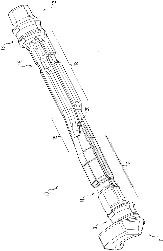
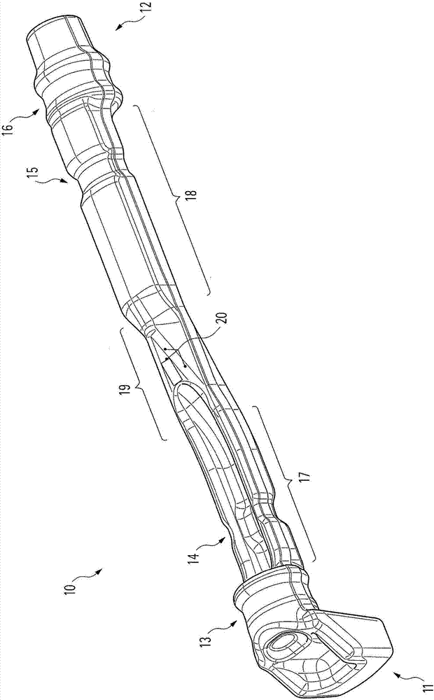
[0029] figure 1 and figure 2 A first embodiment of the balance shaft 10 of the present invention is shown. The balancing shaft 10 comprises two coupling parts 11 , 12 at opposite ends, whereby the balancing shaft 10 can be connected to a drive, in particular a sprocket drive.

[0030] In this embodiment the balancing shaft 10 also comprises four journals 13 , 14 , 15 , 16 for the mounting of radial bearings. The axis of rotation of the balancing shaft 10 is located at the center point of the journals 13 , 14 , 15 , 16 .

[0031] The journals 13 , 16 can each have a bearing inner ring on or at which a bearing (preferably a roller bearing) can be mounted in each case. In this connection it is preferred that the journals 13 , 16 are provided by bearing inner rings integrally formed on the main body, on which the bearings can then be slipped or clamped. For example, a bearing inner ring can be provided in which two correspondingly formed shoulders (not shown) which in combina...


PUM


Abstract

The present invention relates to a balance shaft (10; 10; 100) for balancing an inertial force and / or an moment of inertia of a piston reciprocating internal combustion engine, comprising: at least one elongated body; at least one of which is arranged on the elongated body (13, 14, 15, 16; 13 , 16; 102, 103) for the radial bearing mounting, wherein the axis of rotation of the balance shaft (10; 10 ; 100) (17, 18; 17, 18) are provided on the elongated body, and at least one unbalanced portion (17, 18; 17, 18) is provided on the elongated body, (10; 10;; 100); and on the at least one unbalanced portion (17, 18; 17, 18), the balance axis (10; 10; 100), the material is not substantially set in the area of the axis of rotation. The present invention also relates to a method of manufacturing such a balance shaft.

Description

technical field [0001] The invention relates to a balance shaft for balancing the inertial forces and / or moments of inertia of a piston reciprocating internal combustion engine and to a method for producing such a balance shaft. Background technique [0002] Many balancing shafts are known from the prior art. As a rule, the balancing shaft is produced from a rod-shaped shaft blank by means of hot forming and in particular by swaging. [0003] Such balancing shafts are usually provided in the form of a one-piece solid component, which thus indeed has a high degree of stability, but has a comparatively high component weight. As a result, the balancing shaft has a high mass fraction (Massenanteil), which does not provide a corresponding balancing force during operation, or which mass fraction sometimes has to be compensated by additional mass in order not to cause undesired disturbances during operation. balance. [0004] In contrast, in the development of modern balance sha...

Claims


Application Information

Patent Timeline
Patent Type & Authority Applications(China)
IPC IPC(8): F16F15/26
CPCF16F15/264F16C3/18F16C3/20
Inventor H·布里奇格
Owner HIRSCHVOGEL UMFORMTECHN
Learn More