Device for measuring deformation of relieved end roller of bearing under load

A technology for measuring device and deformation, which is applied in the direction of measuring device, mechanical bearing test, optical device, etc., can solve the problems of lack of design and test basis for roller modification amount, restrict the independent research and development of roller bearings, etc., and improve the test accuracy , Enhance the effect of reflective rate

Inactive Publication Date: 2017-08-04
AVIC HARBIN BEARING
View PDF6 Cites 4 Cited by
  • Summary
  • Abstract
  • Description
  • Claims
  • Application Information

AI Technical Summary

Problems solved by technology

[0003] The content of the present invention is to solve the lack of experimental basis for the design of roller modification amount in the prior art, which restricts the independent research and development of roller bearings based on the use environment, and then provides a bearing modification roller Deformation measuring device under load

Method used


Image

  • Device for measuring deformation of relieved end roller of bearing under load
  • Device for measuring deformation of relieved end roller of bearing under load
  • Device for measuring deformation of relieved end roller of bearing under load

Examples


specific Embodiment approach 1

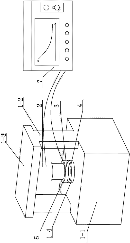
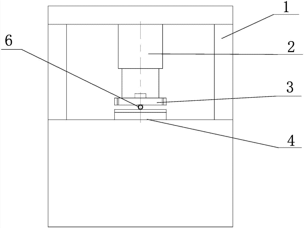
[0010] Specific implementation mode one: combine Figure 1-Figure 3 Describe this embodiment, the device for measuring the amount of deformation of a bearing modifying roller under load described in this embodiment, which includes a test bench body 1, a hydraulic loading system 2, a pressure plate 3, a support plate 4, a controller 7, data recorder 8 and a plurality of optical fiber sensors 5, the test bench body 1 includes a base 1-1, a crossbeam 1-3, a support platform 1-4 and two support columns 1-2, and the two support columns 1-2 are vertical Installed on the upper end surface of the base 1-1, the crossbeam 1-3 is arranged on two support columns 1-2, and one end of the crossbeam 1-3 is installed on the top of a support column 1-2, the crossbeam 1-3 The other end is installed on the top of another support column 1-2, the support platform 1-4 is installed on the base 1-1 between the two support columns 1-2, and the support plate 4 is installed on the support platform 1-4 O...

specific Embodiment approach 2

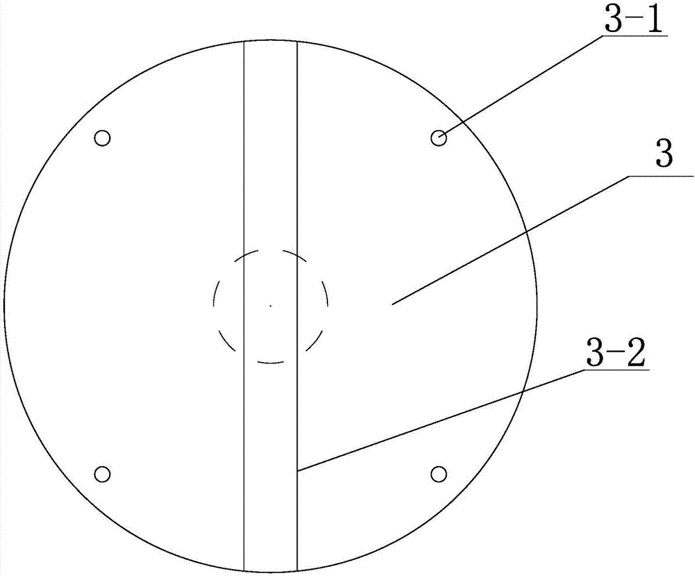
[0013] Specific implementation mode two: combination Figure 1-Figure 3 This embodiment is described. A device for measuring the deformation of a bearing modifying roller under load is described in this embodiment. The pressing plate 3 is processed with a plurality of round holes 3-1 along the circumferential direction, and each round hole 3-1 is equipped with a An optical fiber sensor 5, and others are the same as in the first embodiment.

specific Embodiment approach 3

[0014] Specific implementation mode three: combination Figure 1-Figure 3 Describe this embodiment, a kind of bearing modification roller deformation measurement device under load described in this embodiment, the number of circular holes 3-1 on the pressure plate 3 is four, the number of optical fiber sensors 5 is four . Others are the same as in the second embodiment.


PUM


Abstract

Provided is a device for measuring the deformation of a relieved end roller of a bearing under load. The invention relates to a device for measuring the deformation of a roller under load, and aims to solve the problem that the independent research and development of roller bearings based on working environment is restricted as there is no experimental basis for bearing roller profile modification design in the prior art. The device comprises a test bench body, a hydraulic loading system, a pressure plate, a support plate, a controller, a data recorder, and a plurality of optical fiber sensors. The test bench body comprises a base, a beam, a support platform, and two support columns. The two support columns are vertically installed on the upper end face of the base. The beam is arranged on the two support columns. The support platform is installed on the base between the two support columns. The hydraulic loading system is fixedly installed on the lower end face of the beam. The pressure plate is installed at the bottom of the hydraulic loading system. The multiple optical fiber sensors are uniformly installed on the pressure plate along the circumferential direction. The data recorder is installed on the controller. The device is used in the field of roller deformation measurement under load.

Description

technical field [0001] The invention relates to a device for measuring the amount of deformation of a roller under load, in particular to a device for measuring the amount of deformation of a bearing modification roller under load. Background technique [0002] At present, since there is no corresponding test equipment for the deformation of the bearing modified roller under load, there is a lack of experimental basis for the design of the roller modification amount, and the design of the bearing roller modification amount for different working conditions only relies on experience Selection restricts the independent research and development of the bearing and the custom design based on the use environment, so it is necessary to design a device for measuring the deformation of the bearing modified roller under load. Contents of the invention [0003] The content of the present invention is to solve the lack of experimental basis for the design of roller modification amount ...

Claims


Application Information

Patent Timeline
Patent Type & Authority Applications(China)
IPC IPC(8): G01B11/16G01M13/04
CPCG01B11/16G01M13/04
Inventor 于庆杰公平张静静马芳刘尉韩松
Owner AVIC HARBIN BEARING
Why Eureka
Try Eureka