
Liquid rocket engine turbopump flexible rotor high-speed dynamic balance supporting device

A high-speed dynamic balancing, turbo pump rotor technology, applied in static/dynamic balance testing, measuring devices, machine/structural component testing, etc., can solve the problem of low positioning accuracy, inability to set positioning surfaces, and reduce high-speed dynamic balancing efficiency and other problems, to achieve the effect of ensuring the support stiffness and structural stiffness, avoiding a large amount of oil participating in useless circulation, and simplifying the number of adapters

Active Publication Date: 2017-08-04
BEIJING AEROSPACE PROPULSION INST
View PDF7 Cites 5 Cited by
  • Summary
  • Abstract
  • Description
  • Claims
  • Application Information

AI Technical Summary

Problems solved by technology

At present, the high-speed dynamic balance support device of the hydrogen-oxygen rocket engine turbopump mainly adopts the upper and lower half or two-body separated support structure. The main problems in these structural forms are: 1) The upper and lower half support device cannot be equipped with a positioning surface inside, resulting in The coaxiality of the inner holes of the two supports is poor, which has a negative impact on the high-speed dynamic balance; 2) The structure of the two-body separation type support is complex, and the positioning accuracy is not high; 3) The span of the above two types of support is too large to be suitable for small spans High-speed dynamic balancing of the rotor; 4) The function is single, it can only play a supporting role, and the cooling of the bearing requires two oil inlet pipelines, the utilization rate of the lubricating cooling oil is not high, and the oil consumption is large; 5) There is no cooling oil seal function, which is not conducive to the cleaning of the test bench; 6) The device does not have the function of vibration displacement measurement, and additional equipment is required to reduce the efficiency of high-speed dynamic balancing

Method used


Image

  • Liquid rocket engine turbopump flexible rotor high-speed dynamic balance supporting device
  • Liquid rocket engine turbopump flexible rotor high-speed dynamic balance supporting device
  • Liquid rocket engine turbopump flexible rotor high-speed dynamic balance supporting device

Examples


Embodiment Construction

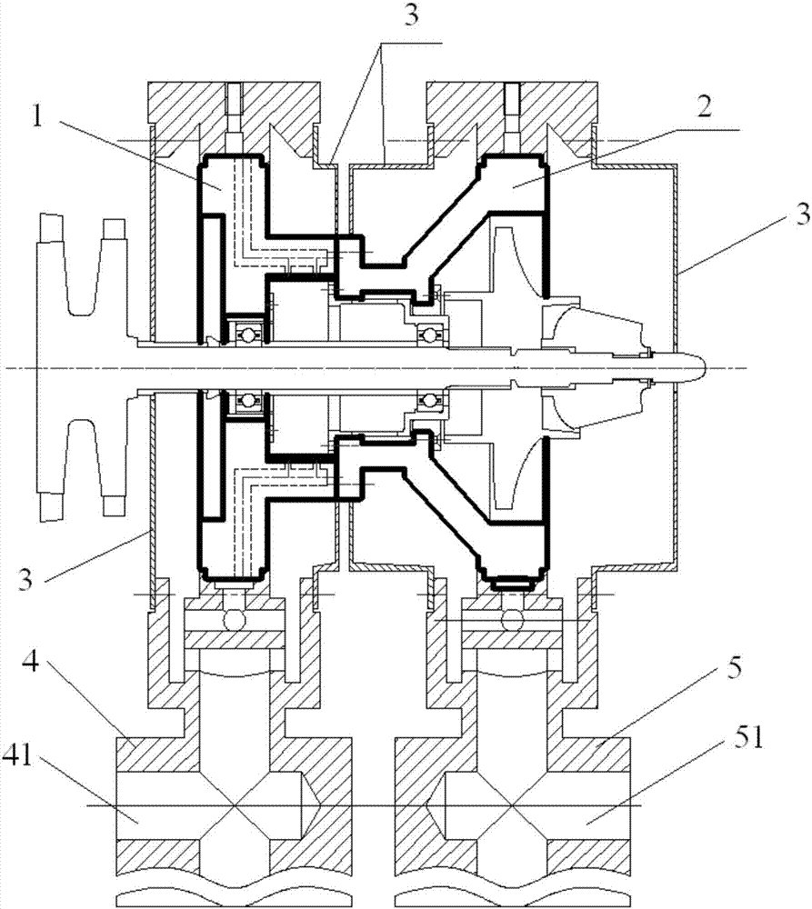
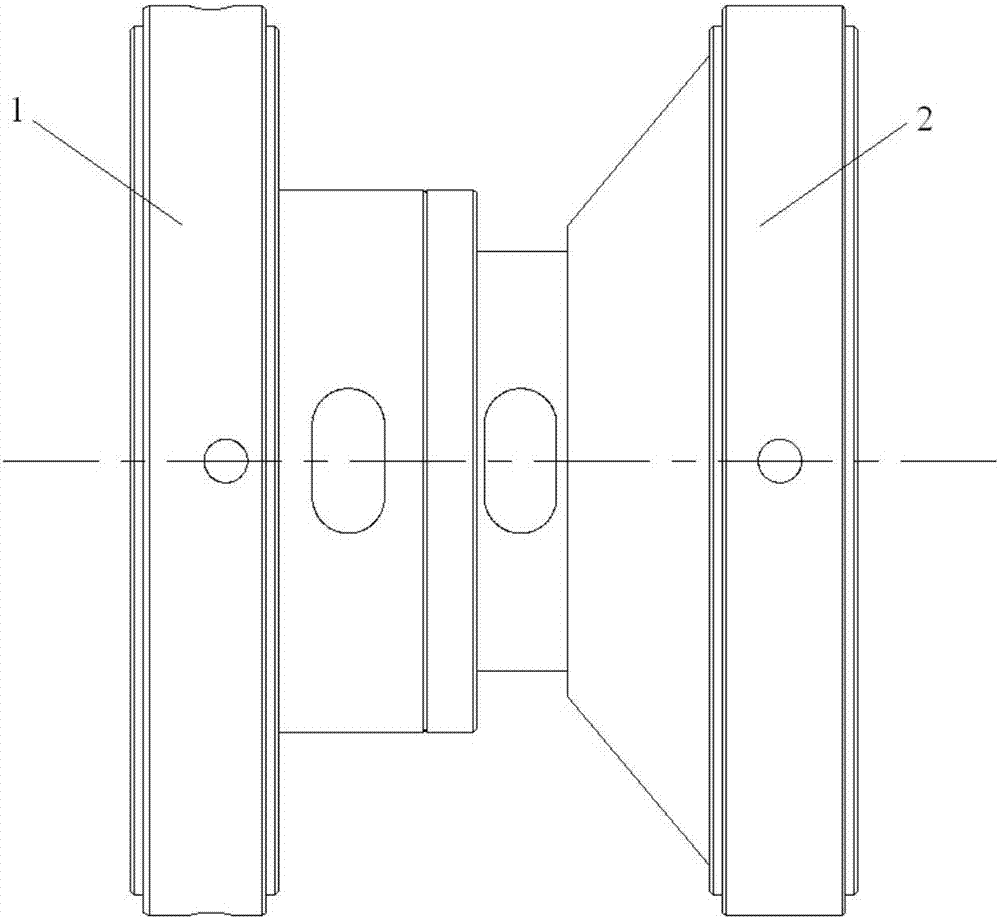
[0026] Such as figure 1 , figure 2 As shown, a high-speed dynamic balance support device for a flexible rotor of a liquid rocket engine turbopump includes a main support case 1, a main support case 2, and an oil seal case 3; a main support case 1 and a main support case 2 2 are complete rotary structures, and the oil seal housing 3 is a rotary structure that is divided into upper and lower halves. During high-speed dynamic balancing, the main support shell 1 and the main support shell 2 are connected as a whole with bolts and installed on the pendulum frame 1 4 and the pendulum frame 2 5, and the supporting structure of the rotor is assembled on the main support shell on the bore flange.

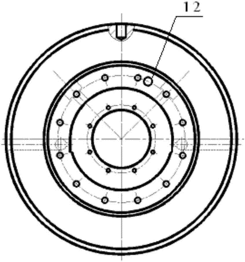
[0027] Such as Figure 3 ~ Figure 6 As shown, the main supporting shell-1 is a stepped rotary body, and the through hole along the axis of the main supporting shell-1 includes three sections, the diameter of the middle section of the through hole is smaller than the diameter of the remai...


PUM


Abstract

The invention provides a liquid rocket engine turbopump flexible rotor high-speed dynamic balance supporting device, including a main support shell I (2), a main support shell II (2) and an oil seal shell (3). The small end of the main support shell II (2) is connected with the small end of the main support shell I (1) through a flange plate of an end part; a turbopump rotor is mounted in a combination structure of connected main support shell I (1) and main support shell II (2) through a bearing; the large ends of the main support shell I (1) and the main support shell II (2) are fixed in annular frames of a swing frame I (4) and a swing frame II (5) respectively; and the oil seal shell (3) is connected with the main support shell I (1), the main support shell II (2), the turbopump rotor, the swing frame I (4) and the swing frame II (5) to form a seal cavity. The liquid rocket engine turbopump flexible rotor high-speed dynamic balance supporting device has a function of lubricating and cooling the bearing with single-support oil taking and bidirectional oil injection and a function of vibration displacement measurement of a rotor.

Description

technical field [0001] The invention relates to a supporting device for a flexible rotor of a turbo pump. Background technique [0002] The turbo pump of the hydrogen-oxygen engine is a key component for transporting liquid hydrogen and liquid oxygen propellants, and its operating status will directly affect the performance and reliability of the engine. Above 20,000r / min, flexible rotor designs that work between the first and second order or even the second and third order critical speeds are often used. The high speed brings challenges to the smooth operation of the turbopump rotor. It must be balanced by high-speed dynamic balancing process so that the rotor can run smoothly at the working speed and the vibration amplitude is within the allowable range of the design. In high-speed dynamic balancing, since there is a certain gap between the radial dimension of the rotor and the inner hole size of the dynamic balancing machine support, it is often far smaller than the inne...

Claims


Application Information

Patent Timeline
Patent Type & Authority Applications(China)
IPC IPC(8): G01M1/04G01M1/16
CPCG01M1/04G01M1/16
Inventor 刘洋窦唯姜绪强闫宇龙李铭涂霆于槟恺
Owner BEIJING AEROSPACE PROPULSION INST
Learn More