Loading device and loading method of geotechnical engineering model test

A technology of model testing and geotechnical engineering, applied in the field of indoor model testing of geotechnical engineering, can solve problems such as difficulties, high loading costs, and simulation of mechanical properties of rock and soil deformation, and achieve convenient operation, low experimental cost, and easy promotion and use Effect

Pending Publication Date: 2017-08-04
FUJIAN UNIV OF TECH
View PDF9 Cites 20 Cited by
  • Summary
  • Abstract
  • Description
  • Claims
  • Application Information

AI Technical Summary

Problems solved by technology

Because the rheological time of rock and soil is long, especially the rheological time of soft soil is as long as several years, in order to simulate the long-term load on the soil, the loading time of indoor model test is often longer, but the above-mentioned equipment is genera

Method used


Image

  • Loading device and loading method of geotechnical engineering model test
  • Loading device and loading method of geotechnical engineering model test
  • Loading device and loading method of geotechnical engineering model test

Examples


Embodiment 1

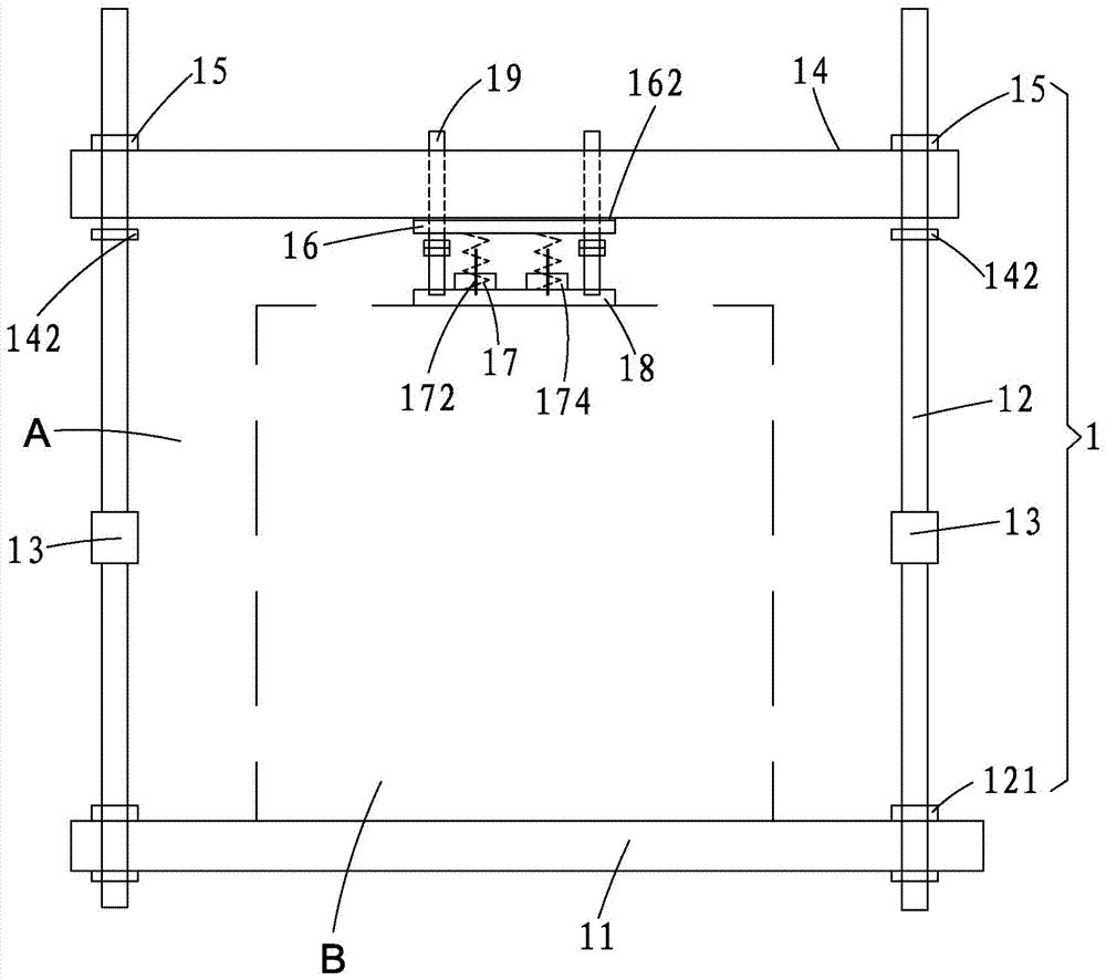
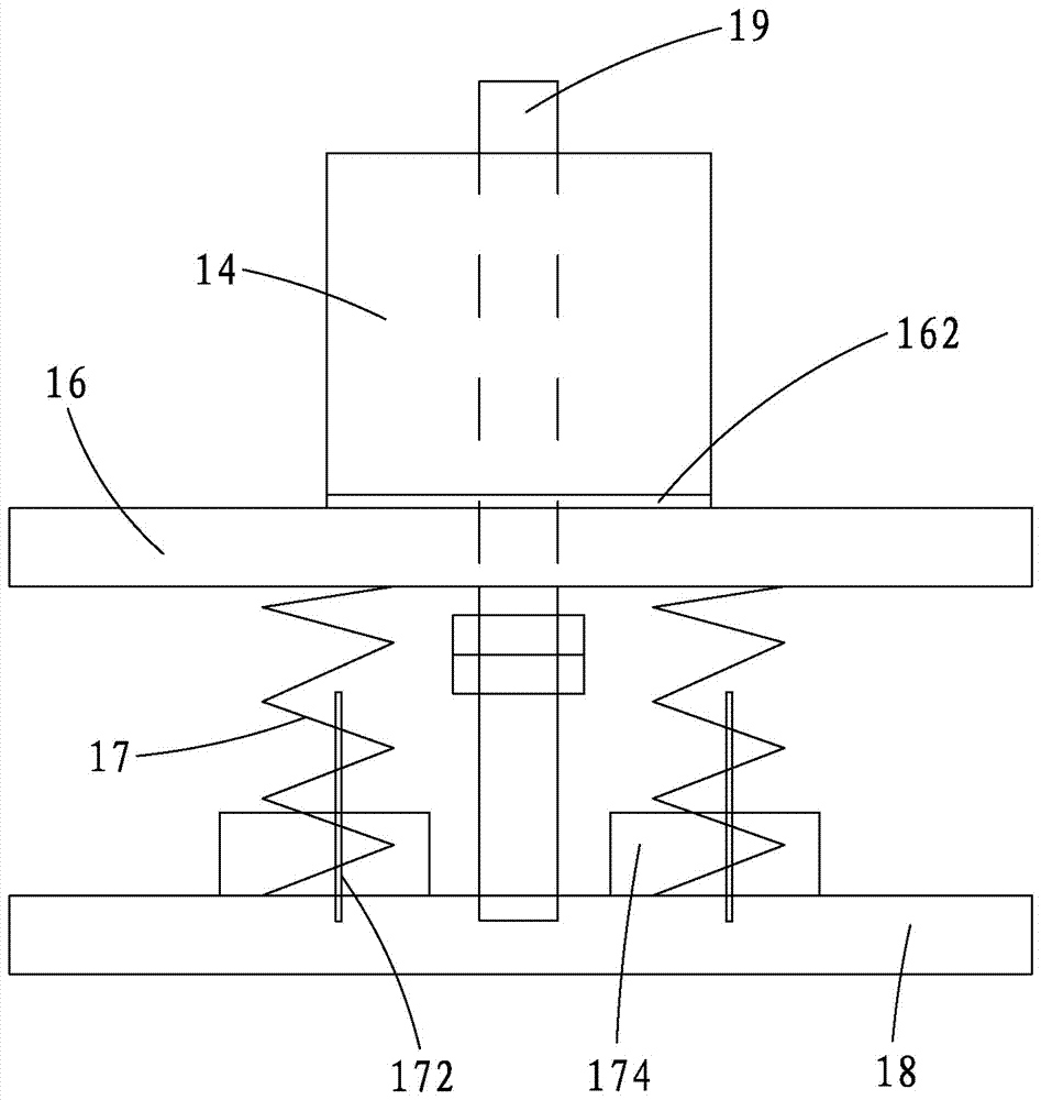
[0046] Such as figure 1 , image 3 As shown, an embodiment of the loading device of the present invention only includes a static loading mechanism 1, and the static loading mechanism 1 includes a ground anchor 11, two reaction force frame columns 12, two force sensors 13, and a reaction force frame crossbeam 14. Two loading bolts 15, a reaction force plate 16, at least two loading springs 17 and a pressure bearing plate 18; the ground anchor 11 is fixed on the ground; the two reaction force frame columns 12 are fixed by column anchor bolts 121 On the ground anchor 11; the two force sensors 13 are respectively connected to the middle section of a reaction force frame column 12; Locked from top to bottom; the reaction force plate 16 is arranged below the reaction force frame beam 14 and is fixedly connected to the pressure bearing plate 18 by the loading spring 17; the ground anchor 11, two reaction force frame columns 12. An accommodating space A for the test model B is enclo...

Embodiment 2

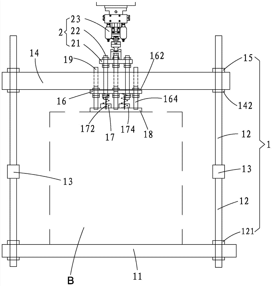
[0060] Such as figure 2 , Figure 4 as well as Figure 5 As shown, one embodiment of the loading device of the present invention includes a static loading mechanism 1 and a dynamic loading mechanism 2, that is, a dynamic loading mechanism 2 is added on the basis of the above-mentioned embodiment 1, and the dynamic loading mechanism 2 includes a terminal plate 21, end plate fixing bolt rod 22 and actuator 23, the end plate 21 and the reaction force plate 16 are connected by the end plate fixing bolt rod 22, and the actuator 23 is connected to the end plate Above the head plate 21; and the reaction force plate 16 is connected with the pressure bearing plate 18 by a reaction force plate fixing bolt rod 164, and the end plate 21, the reaction force plate 16, and the pressure bearing plate 18 are fixed by the end plate fixing bolts After the rods 22 are connected, a space dynamic load transmission system is formed. When the pressure bearing plate 18, the counter force plate 16,...


PUM


Abstract

The invention provides a loading device and a loading method of geotechnical engineering model test. The loading device comprises a static loading mechanism, the static loading mechanism comprises a ground anchor, two reaction frame stand columns, two force sensors, a reaction frame crossbeam, two loading bolts, a reaction plate, at least two loading springs and a pressure bearing plate; the two reaction frame stand columns are fixed on the ground anchor through adopting stand column anchor bolts; the two force sensors are respectively connected to the middle segments of the reaction frame stand columns; the reaction frame crossbeam crosses over the two reaction frame stand columns and is blocked from top to bottom by adopting loading bolts; and the reaction plate is arranged below the reaction frame crossbeam and is fixedly connected with the pressure bearing plate through the loading springs, the device can also comprise a dynamic loading mechanism, and the dynamic loading mechanism comprises a header plate, header plate fixing bolt rods and an actuator. The device and the method can realize the static creep deformation test of a geotechnical engineering model, or the coupling loading of the static creep deformation test and dynamic fatigue test.

Description

[0001] 【Technical field】 [0002] The invention relates to a geotechnical engineering indoor model test technology, in particular to a loading device and a loading method for a geotechnical engineering model test. [0003] 【Background technique】 [0004] Rock soil and underground structures are often subjected to static loads and dynamic loads at the same time. For example, the railway subgrade bears static loads such as the track and its soil weight and the dynamic load transmitted by the high-speed train through the track. Long-term static loads cause rheological deformation of rock and soil, while intermittent dynamic loads cause dynamic cumulative deformation of rock and soil. Fully understanding the rheological and dynamic deformation characteristics of rock and soil materials is the key to ensuring engineering safety and stability. important prerequisite. Therefore, it is of great practical significance to study the physical mechanics and deformation characteristics of r...

Claims


Application Information

Patent Timeline
IPC IPC(8): G01N3/02
CPCG01N3/02G01N2203/0026
Inventor 王启云张丙强陈军浩雷虎军臧万军马永超赵卫华施惠容
Owner FUJIAN UNIV OF TECH
Why Eureka
Try Eureka