
A test system for LED photoelectric and thermal characteristics and its application

Inactive Publication Date: 2019-08-09
SHANDONG UNIV
View PDF9 Cites 0 Cited by
  • Summary
  • Abstract
  • Description
  • Claims
  • Application Information

AI Technical Summary

Problems solved by technology

The pin temperature method needs to measure the pin temperature, chip power dissipation and thermal resistance coefficient. Because the chip power dissipation and thermal resistance coefficient are inaccurate, the measurement accuracy is relatively low; the infrared imaging method can only test unpackaged chips, which cannot be realized. Non-destructive measurement of LED devices. At the same time, infrared imaging technology is affected by factors such as the light emissivity of the tested LED device and environmental humidity, and the test error is relatively large; the luminescence spectrum peak shift method requires high resolution of the spectrometer. It is difficult to measure the accuracy, and the measurement accuracy and repeatability are relatively low; the voltage method is to set a constant ambient temperature under a specific current, so that the LED junction temperature is equal to the ambient temperature, and according to the relationship between the forward voltage drop of the LED and the temperature of the LED chip Linear relationship, measure the forward voltage of two points with a temperature interval greater than 50 degrees, so as to determine the relationship between the LED voltage and temperature, the voltage method can realize the non-destructive test of the junction temperature of the LED device, but its measurement accuracy needs to be further improved improve
[0004] In addition, the optical parameter measurement of the LED test system in the prior art needs to manually adjust various parameters such as current, voltage, temperature, etc., and the measurement system for the optical characteristics and thermal characteristics of the LED is separated, and each part needs to be measured separately, and the measurement process is complicated.

Method used


Image

  • A test system for LED photoelectric and thermal characteristics and its application
  • A test system for LED photoelectric and thermal characteristics and its application
  • A test system for LED photoelectric and thermal characteristics and its application

Examples


Embodiment 1

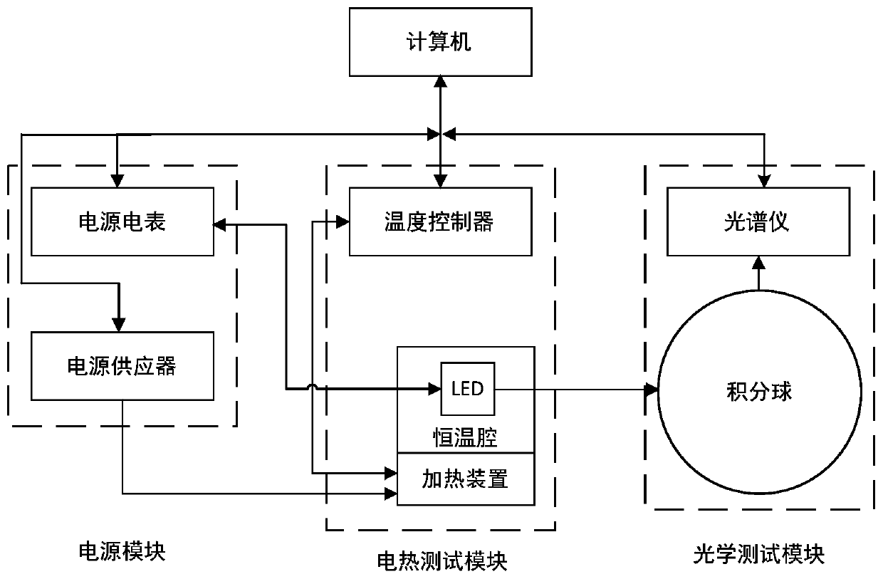
[0046] Such as figure 1 shown.

[0047] A test system for LED photoelectric and thermal characteristics, including a computer, a power supply module, an electrothermal test module and an optical test module; the computer is respectively connected to the power supply module, the electrothermal test module and the optical test module; Connect to the optical test module.

Embodiment 2

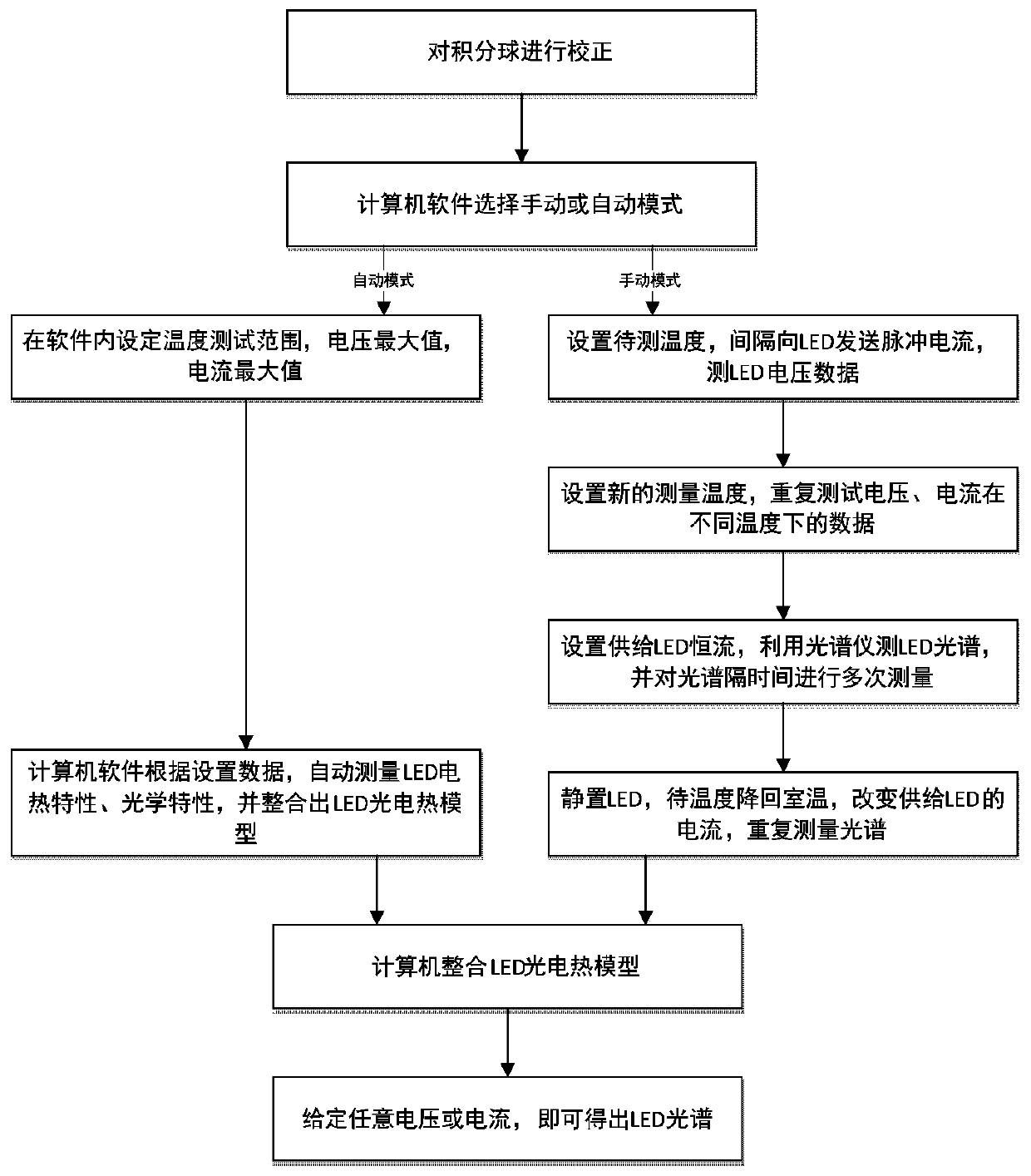
[0049] Such as figure 2 shown.

[0050] The test system for LED photoelectric thermal characteristics as described in Example 1, the difference is that the power module includes a power meter and a power supply; the electrothermal test module includes a constant temperature chamber, a heating device and a temperature controller, and the constant temperature chamber An LED is arranged inside; the optical test module includes an integrating sphere and a spectrometer; the power meter is connected to the computer and the LED respectively, and the computer is connected to the heating device through a power supply; the temperature controller is connected to the heating device and the computer respectively; The integrating sphere is respectively connected with the spectrometer and the LED, and the spectrometer is connected with the computer. When measuring the relationship between I / V and temperature, the power supply ammeter supplies LED pulse current, and when measuring the spect...

Embodiment 3

[0053] The test system for the photoelectric and thermal characteristics of LEDs described in Example 2 is different in that an LED lamp holder is provided on the integrating sphere.


PUM


Abstract

The invention relates to a system for testing the electrothermal characteristics of LED light, and an application of the system. The system comprises a computer, a power module, an electrothermal testing module and an optical testing module. The computer is connected with the power module, the electrothermal testing module and the optical testing module. The power module is also connected with the electrothermal testing module and the optical testing module. The system improves a voltage method, measures a plurality of temperatures and different currents under the same temperature, obtains the more precise temperature / voltage relation, and improves the testing accuracy.

Description

technical field [0001] The invention relates to a testing system for the photoelectric and thermal characteristics of LEDs and an application thereof, belonging to the technical field of LED performance testing. Background technique [0002] Compared with traditional light sources, LED has many advantages, and has become the most promising solid light source at present, and is widely used in various fields of production and life. How to quickly and accurately test the optical characteristics of LEDs under different electrothermal conditions plays an important role in the rapid development of the LED industry, and the measurement of LED junction temperature is an important part of testing the photoelectric and thermal characteristics of LEDs. [0003] At present, the testing methods of LED junction temperature mainly include pin temperature method, infrared imaging method, luminous spectrum peak shift method and voltage method. The pin temperature method needs to measure the...

Claims


Application Information

Patent Timeline
Patent Type & Authority Patents(China)
IPC IPC(8): G01R31/26G01M11/02
CPCG01M11/02G01R31/2635
Inventor 孔繁敏张宁
Owner SHANDONG UNIV
Learn More