Compressor stator, permanent magnet motor, compressor and stator coil winding method

A technology for compressors and stators, applied in the field of compressor manufacturing, which can solve the problems of increased friction of multi-strand wires, reduced slot fullness, high difficulty, etc. high efficiency effect

Pending Publication Date: 2017-08-04
GUANGDONG MEIZHI COMPRESSOR
View PDF5 Cites 10 Cited by
  • Summary
  • Abstract
  • Description
  • Claims
  • Application Information

AI Technical Summary

Problems solved by technology

Since the process of paralleling multi-strand enameled wires is relatively difficult, multi-strand wires are generally selected for winding through a single-hole winding nozzle, which requires increased winding tension and increased friction between multi-strand wires, which is prone to wire Injury, affecting the quality of the motor
At the same time, double-wire winding increases the maximum inner diameter of the winding nozzle. When the winding nozzle maintains a certain strength, the width of the winding nozzle must be increased. When the stator core mold remains unchanged, the slot size remains unchanged. During the winding process, it is easy to have the problem that the winding wire hits the winding nozzle. What is more important is that during the winding process, multiple strands of enameled wire are wound together and tend to cross, resulting in a large gap between the coils, which greatly reduces the slot fill rate and seriously affects the motor. performance
[0003] In the related art, in order to solve the above problems, some solutions set multiple separate wire outlet holes in a single winding nozzle, so that each strand of wire uses a separate wire outlet hole, and at the same time, the size of each hole along the axial direction of the hole is based on the actual wire winding. The setting of the situation is different, which can reduce the damage point of the wire, and can also reduce the crossover phenomenon, but the requirement for precision is particularly high. , high difficulty, time-consuming, difficult to achieve mass production, there is room for improvement

Method used


Image

  • Compressor stator, permanent magnet motor, compressor and stator coil winding method
  • Compressor stator, permanent magnet motor, compressor and stator coil winding method
  • Compressor stator, permanent magnet motor, compressor and stator coil winding method

Examples


Embodiment Construction

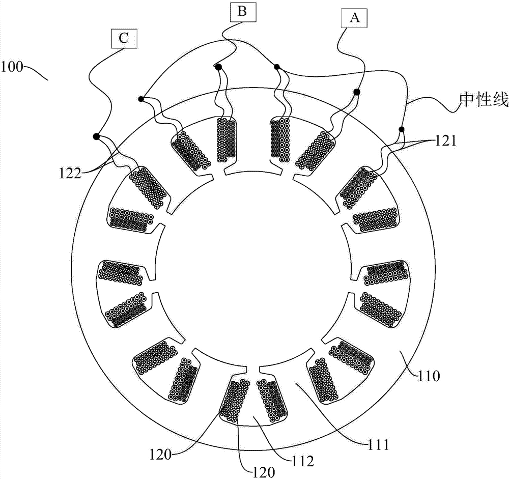
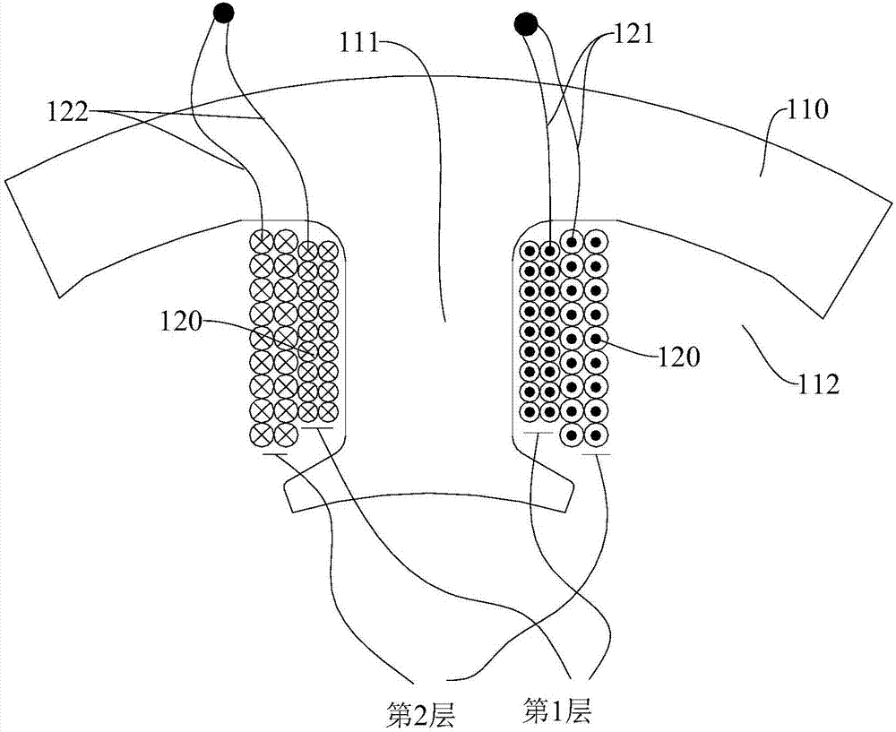
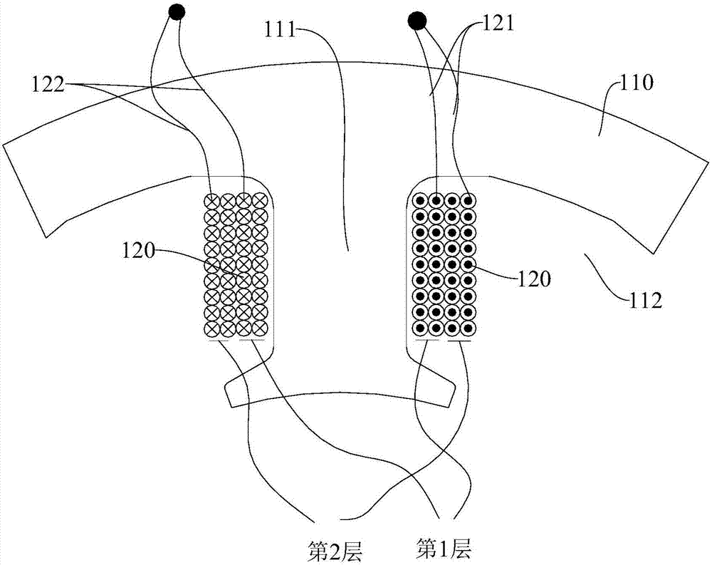
[0032] Embodiments of the present invention are described in detail below, examples of which are shown in the drawings, wherein the same or similar reference numerals designate the same or similar elements or elements having the same or similar functions throughout. The embodiments described below by referring to the figures are exemplary only for explaining the present invention and should not be construed as limiting the present invention.

[0033] In describing the present invention, it should be understood that the terms "center", "longitudinal", "transverse", "length", "width", "thickness", "upper", "lower", "front", " Back", "Left", "Right", "Vertical", "Horizontal", "Top", "Bottom", "Inner", "Outer", "Clockwise", "Counterclockwise", "Axial", The orientation or positional relationship indicated by "radial", "circumferential", etc. is based on the orientation or positional relationship shown in the drawings, and is only for the convenience of describing the present invent...


PUM


Abstract

The present invention discloses a compressor stator, a permanent magnet motor, a compressor and a stator coil winding method. The stator comprises a stator iron core and coils. The stator iron core is provided with a plurality of circumferentially spaced winding teeth and a winding slot is formed between every two adjacent winding teeth. M coils are sequentially wound onto each winding tooth from the inside to the outside, wherein the line outgoing taps of the m coils for each winding tooth are connected, and the line incoming taps of the m coils for each winding tooth are connected. M is larger than or equal to 2. According to the technical scheme of the invention, during the winding process, coils are not easily scratched or knotted, and are arranged more orderly. Meanwhile, the production efficiency is high, and the manufacturability is improved. The slot fullness rate of the motor is improved.

Description

technical field [0001] The invention belongs to the technical field of compressor manufacturing, and in particular relates to a stator of a compressor, a permanent magnet motor with the stator, a compressor with the permanent magnet motor, and a winding method for stator coils of the compressor. Background technique [0002] In the motor manufacturing process, low-voltage and high-current motors are generally wound in parallel or parallel or a combination of the two. Since the process of paralleling multi-strand enameled wires is relatively difficult, multi-strand wires are generally selected for winding through a single-hole winding nozzle, which requires increased winding tension and increased friction between multi-strand wires, which is prone to wire Injury will affect the quality of the motor. At the same time, double-wire winding increases the maximum inner diameter of the winding nozzle. When the winding nozzle maintains a certain strength, the width of the winding n...

Claims


Application Information

Patent Timeline
IPC IPC(8): H02K1/16H02K3/12H02K3/28H02K15/085
CPCH02K1/16H02K3/12H02K3/28H02K15/085H02K2213/03
Inventor 毛临书乔正忠邱小华
Owner GUANGDONG MEIZHI COMPRESSOR
Why Eureka
Try Eureka