
Correction device and correction method capable of improving tracking precision of pinch roller of reeling machine

A technology of tracking accuracy and correction method, which is applied in the field of hot rolling and coiling technology, can solve the problems of unreachable pressure, difficult maintenance, unstable pressure signal of pinch roll, etc., so as to reduce the cost of production and spare parts, improve tracking accuracy, low cost effect

Active Publication Date: 2017-08-08
BAOSHAN IRON & STEEL CO LTD
View PDF10 Cites 8 Cited by
  • Summary
  • Abstract
  • Description
  • Claims
  • Application Information

AI Technical Summary

Problems solved by technology

[0007] In order to solve the problem that when the middle part of the pinch roll is worn out in the prior art, when the head of the strip hits the pinch roll, although the pressure detection device of the pinch roll can detect slight pressure fluctuations, the pressure cannot reach or exceed the limit. Amplitude, resulting in the problem that the position of the strip head cannot be corrected, and the installation of a laser detection device has high environmental requirements and difficult maintenance
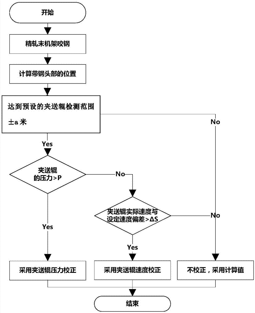
The invention provides a correction device and correction method for the tracking accuracy of pinch rollers in a coiler. The calculated position of the head of the strip is corrected through changes in the pressure of the pinch rollers and the speed of the pinch rollers, so as to solve the problem of pinch rollers. The problem of unstable pressure signal of the feeding roller can achieve the purpose of improving the tracking accuracy of the coiler

Method used


Image

  • Correction device and correction method capable of improving tracking precision of pinch roller of reeling machine
  • Correction device and correction method capable of improving tracking precision of pinch roller of reeling machine

Examples


Embodiment

[0041] Take the 2050 unit coiling unit for steel production as an example.

[0042] Pinch roller detection range a value: 3.5 meters;

[0043] Limit value P value: 12KN;

[0044] Deviation ΔS value: 0.1m / s. The specific implementation steps are as follows:

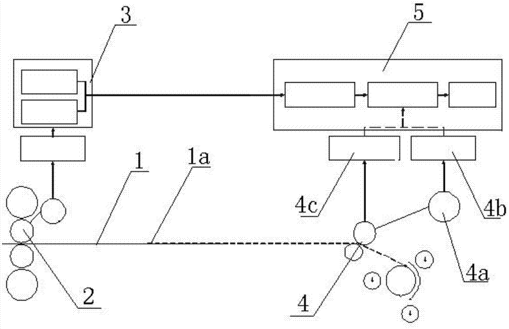
[0045] 1) When the strip steel 1 bites into the final stand 2 of the finishing mill, the basic automation computer for finishing rolling 3 sends the steel strip bite signal, roll diameter and rotational speed to the coiling basic automation computer 5, and the coiling basic automation computer Calculate the position of the strip head 1a according to the obtained steel bite signal, roll diameter and rotating speed;

[0046] 2) Judgment of signal reliability: In order to prevent wrong tracking and correction caused by wrong signals, the credibility of the pressure detection signal obtained by the pinch roller pressure detection device 4c of the pinch roller assembly 4 and the pinch roller speed reduction signal is judged ...


PUM


Abstract

The invention discloses a correction device and correction method capable of improving tracking precision of a pinch roller of a reeling machine. The device comprises strip steel, a finishing mill group end rack and a finishing mill basic automatic computer, wherein the finishing mill basic automatic computer is in signal communication with the finishing mill basic automatic computer; the finishing mill basic automatic computer is in signal communication with a reeling basic automatic computer arranged at the position of a pinch roller assembly; the pinch roller assembly is provided with a pinch roller rotating speed measuring device at the position of a pinch roller motor, the pinch roller rotating speed measuring device is in signal communication with the reeling basic automatic computer, and obtained pinch roller actual rotating speed is sent to the reeling basic automatic computer to be compared. Through changes of pinch roller pressure and pinch roller speed, the calculated head position of the strip steel is corrected, and the problem that after a pinch roller is worn, pressure signals are not stable is solved; the tracking precision of the reeling machine is improved; the correction device and correction method have the beneficial effects that existing equipment is small in modification, the cost is low, and production and spare part cost is greatly reduced.

Description

technical field [0001] The invention relates to a hot rolling coiling process in the field of iron and steel production, in particular to a correction device and a correction method applied to a pinch roll of a coiler and capable of improving the tracking accuracy of the pinch roll of a coiler. Background technique [0002] At present, in various iron and steel production enterprises, the coiler is an important equipment of the hot rolling production line, which is used to coil the hot rolled steel strip into steel coils. The coiler is located behind the finish rolling unit and is the last process of the hot continuous rolling production line. The coiler mainly includes main equipment such as roller tables, side guide plates, pinch rollers, reels, and auxiliary coiling rollers. Among them, the roller table is mainly responsible for transporting the strip steel from the finishing rolling unit to the coiler unit. The main function of the side guides is to center the strip. T...

Claims


Application Information

Patent Timeline
Patent Type & Authority Applications(China)
IPC IPC(8): B21C47/02B21C47/34
CPCB21C47/003B21C47/02B21C47/34
Inventor 李海东幸利军
Owner BAOSHAN IRON & STEEL CO LTD
Learn More