Pressure expander blade, compressor structure and compressor

A diffuser and compressor technology, applied in the field of compressors, can solve the problems of airflow mixing loss, reduce the aerodynamic efficiency of the compressor, and the large low-speed and low-energy area of ​​the blade, so as to reduce the airflow mixing loss and improve the aerodynamic efficiency.

Pending Publication Date: 2017-08-08
GREE ELECTRIC APPLIANCES INC
View PDF7 Cites 4 Cited by
  • Summary
  • Abstract
  • Description
  • Claims
  • Application Information

AI Technical Summary

Problems solved by technology

However, due to the difference in air velocity and direction between the mainstream and the supplementary air flow in the current supplementary air scheme, the supplementary air produces a large airflow mixing loss and reduces the aerodynamic efficiency of the compressor.
[0004] In addition, in a centrifugal compressor, the use of a vane diffuser can effectively improve the aerodynamic performance of the compressor at the design point.
[0005] The blades generate large low-speed and low-energy areas, which eventually lead to compressor stall and surge, reducing the stable operating range of the compressor
Although the compressor has a wide range of operation using a vaneless diffuser, the performance of the design point is low

Method used


Image

  • Pressure expander blade, compressor structure and compressor
  • Pressure expander blade, compressor structure and compressor
  • Pressure expander blade, compressor structure and compressor

Examples


Embodiment Construction

[0022] The present invention will be described in further detail below in conjunction with the accompanying drawings and specific embodiments, but not as a limitation of the present invention.

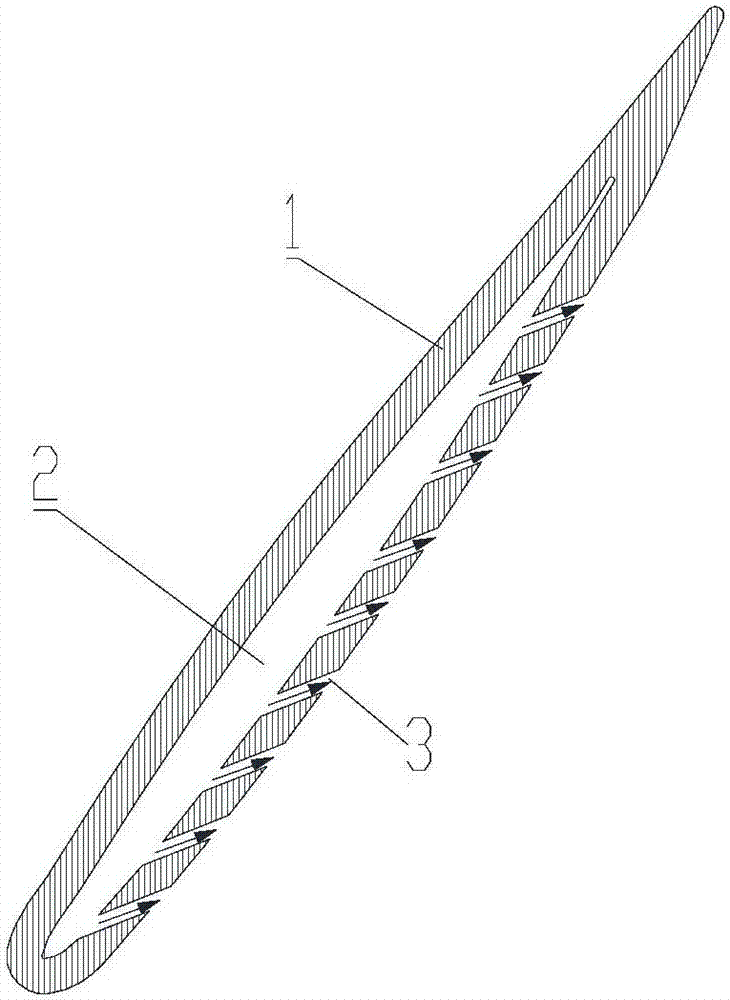
[0023] The purpose of the invention is to reduce the air mixing loss caused by supplementary air, and expand the operating range of the compressor while improving the performance of the design point. To this end, the embodiment of the present invention provides a diffuser vane, comprising: a vane body 1 , a cavity 2 is formed inside the vane body 1 , and an air supply hole 3 is formed on the vane body 1 . Preferably, the air supply holes 3 are arranged on the suction surface of the blade body 1 . Preferably, the blade body 1 is made by casting or machining.

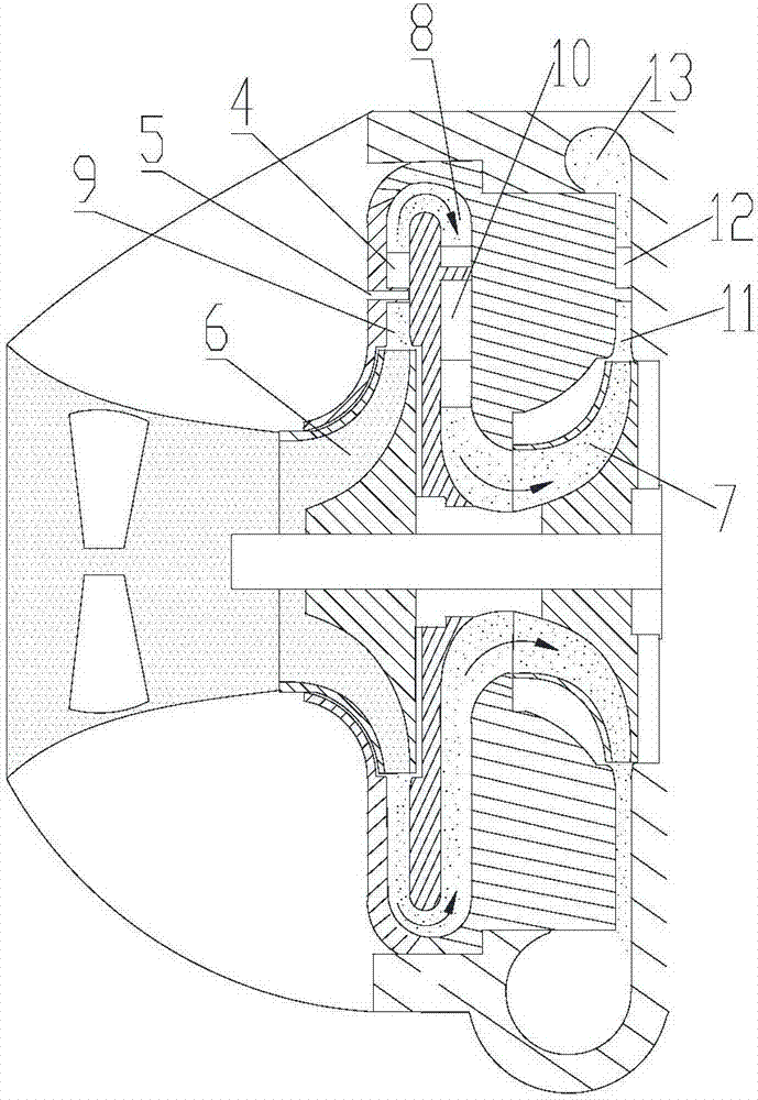
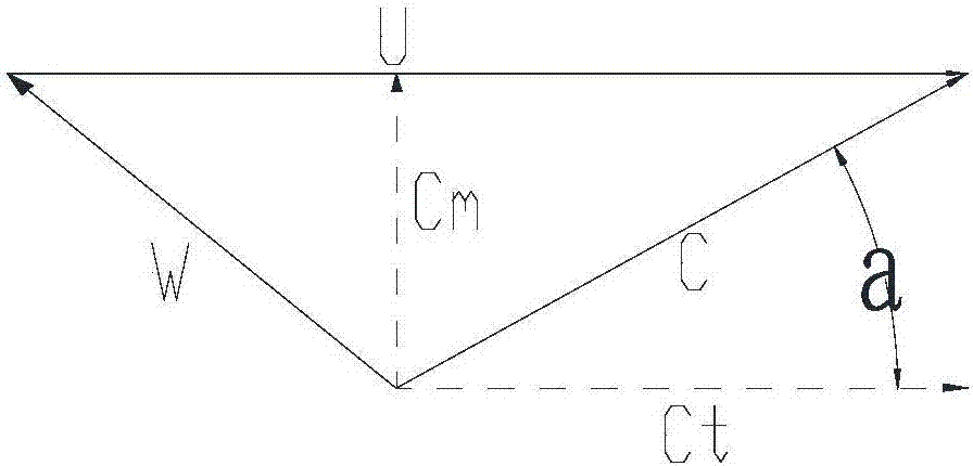
[0024] Please refer to Figure 1-3 , when the compressor is running at the design point, after the gas refrigerant passes through the first-stage impeller 6, since the refrigerant moves in a circle with the impeller, the absolut...


PUM


Abstract

The invention discloses a pressure expander blade, a compressor structure and a compressor. The pressure expander blade comprises a blade body, and a cavity is formed in the blade body. Air supplementing holes are formed in the blade body. According to the pressure expander blade, the compressor structure and the compressor, jet flow can be formed on the suction surface of the pressure expander blade by means of air supplementing through the pressure expander blade of the hollow structure and the air supplementing holes in the back portion of the pressure expander blade so as to blow down a low-speed and low-energy area formed on the suction surface, airflow mixing losses caused by air supplementing are reduced, and therefore aerodynamic efficiency of the centrifugal compressor is improved, and the operation range of the compressor can be widened while the aerodynamic performance of compressor design points is improved.

Description

technical field [0001] The invention relates to the field of compressors, in particular to a diffuser vane, a compressor structure and a compressor. Background technique [0002] In a centrifugal compressor, since the temperature of the gas will rise sharply after being compressed, the specific volume of the gas is very large at high temperature, and the energy consumption of the compressor will increase sharply under the condition of ensuring the same cooling capacity. In order to reduce the power consumption of the compressor and increase the refrigeration capacity, a multi-stage compression refrigeration cycle is commonly used. [0003] The most widely used at present is the "two-stage compression intermediate incomplete cooling refrigeration cycle" with a flash vapor separator (commonly known as an economizer). The two-stage compression refrigeration cycle is to mix the flash steam separated from the economizer with the exhaust gas from the low-stage compression, which ...

Claims


Application Information

Patent Timeline
Patent Type & Authority Applications(China)
IPC IPC(8): F04D29/44F04D29/42F04D29/66
CPCF04D29/4206F04D29/444F04D29/661F04D29/684F04D29/284
Inventor 刘增岳钟瑞兴蒋楠蒋彩云陈玉辉周义雷连冬欧阳鑫望
Owner GREE ELECTRIC APPLIANCES INC
Why Eureka
Try Eureka