
Double-wall cooling device and application

A cooling device and double-walled technology, applied in the field of aero-engines, can solve the problems of large consumption of cold air, large flow resistance of cold air passages, unfavorable cold air outflow of corrugated plate structure, etc., to achieve high cooling efficiency, less cooling air volume, Low flow resistance effect

Inactive Publication Date: 2022-07-29
NORTHWESTERN POLYTECHNICAL UNIV
View PDF4 Cites 0 Cited by
  • Summary
  • Abstract
  • Description
  • Claims
  • Application Information

AI Technical Summary

Problems solved by technology

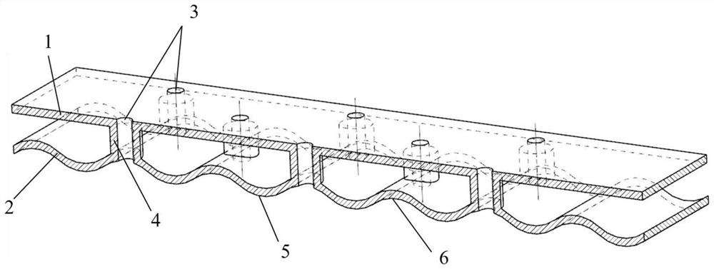
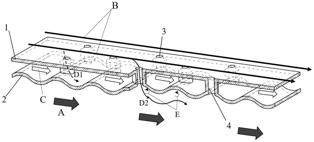
[0009]In order to avoid the disadvantages of the prior art, the present invention provides a double wall cooling device, the cold side plate and the hot side corrugated plate pass through the hollow spoiler Connectivity solves the problem that the traditional corrugated plate structure consumes a lot of cold air, and the flow resistance of the cold air channel is large, which is not conducive to the outflow of cold air downstream of the corrugated plate structure.

Method used


Image

  • Double-wall cooling device and application
  • Double-wall cooling device and application
  • Double-wall cooling device and application

Examples


Embodiment Construction

[0033] The embodiments described below with reference to the accompanying drawings are exemplary, and are intended to explain the present invention and should not be construed as limiting the present invention.

[0034] In the description of the present invention, it should be understood that the terms "center", "longitudinal", "lateral", "length", "width", "thickness", "upper", "lower", "front", " rear, left, right, vertical, horizontal, top, bottom, inside, outside, clockwise, counterclockwise, etc., or The positional relationship is based on the orientation or positional relationship shown in the accompanying drawings, which is only for the convenience of describing the present invention and simplifying the description, rather than indicating or implying that the referred device or element must have a specific orientation, be constructed and operated in a specific orientation, Therefore, it should not be construed as a limitation of the present invention.

[0035] This imp...


PUM

PropertyMeasurementUnit
Wall thicknessaaaaaaaaaa

Abstract

The invention discloses a double-wall cooling device and application, and belongs to the field of aero-engines. Comprising a cold side flat plate, a hot side corrugated plate and hollow turbulent flow columns, the cold side flat plate is located on one side of a cold air channel, the hot side corrugated plate is located on one side of a high-temperature fuel gas channel, and an inverted hill-shaped middle channel with the sectional area changing periodically is formed between two layers of wall plates; a plurality of hollow turbulent flow columns are arranged between the cold side flat plate and the hot side corrugated plate, the cold air channel is communicated with the high-temperature fuel gas channel, and the connecting positions of the hollow turbulent flow columns and the hot side corrugated plate are located on the wave crests of the hot side corrugated plate. Hollow column turbulent flow cooling and external air film cooling are combined, the purpose of high cooling efficiency is achieved by using less cold air, meanwhile, the internal thermal stress of the structure is reduced, and the flow resistance of the structure is reduced. And meanwhile, the defect that a traditional corrugated plate cold air channel is large in flow resistance is overcome, and the problem that outflow cannot be achieved due to insufficient cold air total pressure of a downstream heat screen and a spray pipe heat screen is effectively solved.

Description

technical field [0001] The invention belongs to the field of aero-engines, and in particular relates to a double-wall cooling device and application. Background technique [0002] The working environment of the afterburner and the high-temperature components behind it is harsh, and the gas temperature in the afterburner after the afterburner is ignited and reignited can be as high as 2050K-2100K, or even higher. Afterburner is usually turned on and off for a short period of time, and thermal stress and thermal deformation caused by temperature distribution and changes need to be considered. In addition, the oscillating combustion in the afterburner can also seriously affect its service life and must also be taken into account when designing the cooling structure. [0003] Longitudinal corrugated heat shield is one of the commonly used heat shields for afterburners. It has the advantages of reducing thermal stress and high cooling efficiency of cold air retention. In order ...

Claims


Application Information

Patent Timeline
IPC IPC(8): F28F13/06F23R3/00
CPCF28F13/06F23R3/00F23R2900/03042Y02T50/60
Inventor 朱惠人徐志鹏张丽周道恩郭涛
Owner NORTHWESTERN POLYTECHNICAL UNIV
Learn More