Parallel type pulse tube machine

A parallel, pulse tube technology, applied in refrigerators, compressors, gas cycle refrigerators, etc., can solve the problems of reducing economic costs, complex and disadvantageous structure of refrigerators, improve work efficiency, and avoid uneven temperature distribution. , the effect of increasing the cooling capacity

Active Publication Date: 2017-08-08
TONGJI UNIV
View PDF7 Cites 2 Cited by
  • Summary
  • Abstract
  • Description
  • Claims
  • Application Information

AI Technical Summary

Problems solved by technology

In order to increase the cooling capacity, the above-mentioned patent discloses the method of connecting two cold heads in parallel, and uses the push piston to recover the expansion work. However, the push piston used in this method is a moving part, which makes the structure of the refrigerator more complicated, which is not conducive to reducing the cooling capacity. economic cost

Method used


Image

  • Parallel type pulse tube machine
  • Parallel type pulse tube machine
  • Parallel type pulse tube machine

Examples


Embodiment 1

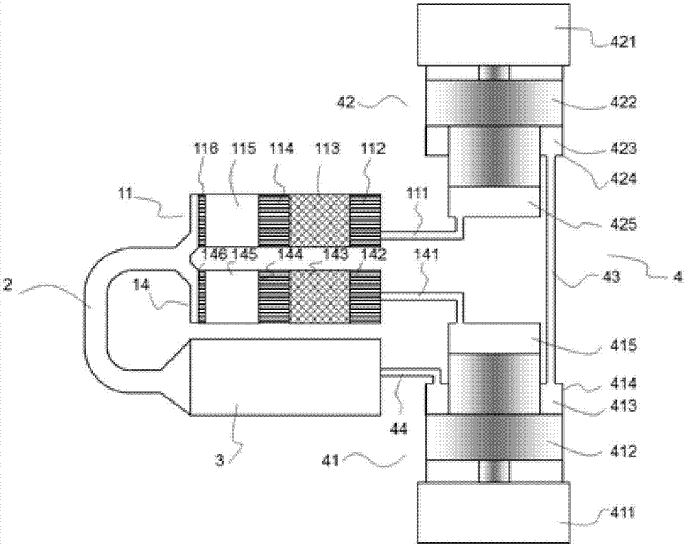
[0036] Such as figure 1 As shown, the parallel pulse tube refrigerator is composed of a cold head 11, a cold head 14, an inertia tube 2, a gas storage 3 and a compressor 4. The compressor 4 is composed of a stepped compressor 41 , a stepped compressor 42 , a second connecting pipe 43 and a connecting pipe 44 .

[0037] The cold head 11 is formed by connecting the first connecting pipe 111, the hot end heat exchanger 112, the regenerator 113, the cold end heat exchanger 114, the pulse tube 115 and the pulse tube hot end heat exchanger 116 in sequence, and the gas can be Free flow within each part.

[0038] The cold head 14 is formed by connecting the first connection pipe 141, the hot end heat exchanger 142, the regenerator 143, the cold end heat exchanger 144, the pulse tube 145 and the pulse tube hot end heat exchanger 146 in sequence, and the gas can be Free flow within each part.

[0039] The cold head 11 and the cold head 14 are connected to the inertia tube 2 and the gas...

Embodiment 2

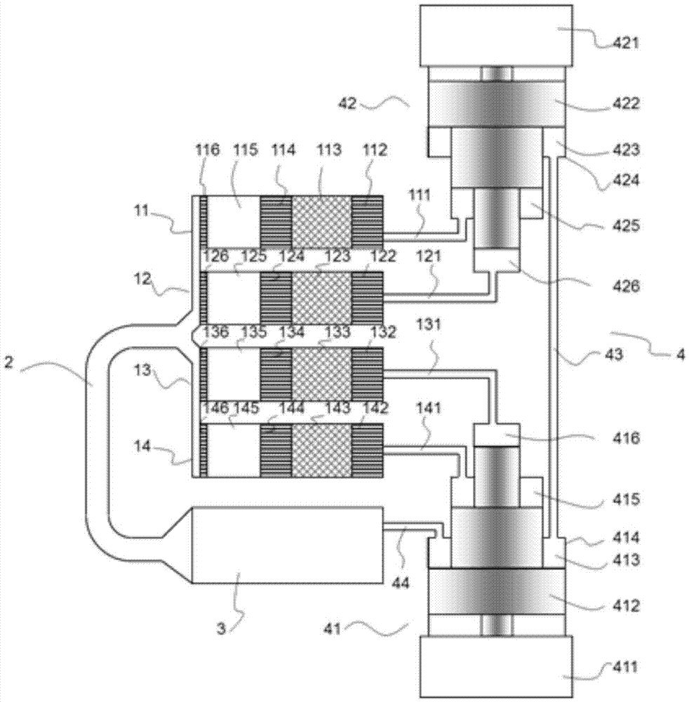
[0044] Such as figure 2 As shown, in the parallel pulse tube refrigerator, on the basis of Embodiment 1, the n-stage stepped piston 412 and the n-stage stepped piston 422 are respectively increased by one step. Correspondingly, the stepped compressor 41 and the stepped compressor 42 are respectively The compression chamber 416 and the compression chamber 426 are added, and the cold head 12 and the cold head 13 are added correspondingly.

[0045] Wherein, the cold head 12 is formed by sequentially connecting the first connecting pipe 121, the hot end heat exchanger 122, the regenerator 123, the cold end heat exchanger 124, the pulse tube 125 and the pulse tube hot end heat exchanger 126. Can flow freely in all parts.

[0046] The cold head 13 is connected in sequence by the first connecting pipe 131, the hot end heat exchanger 132, the regenerator 133, the cold end heat exchanger 134, the pulse tube 135 and the pulse tube hot end heat exchanger 136. Free flow within each par...

Embodiment 3

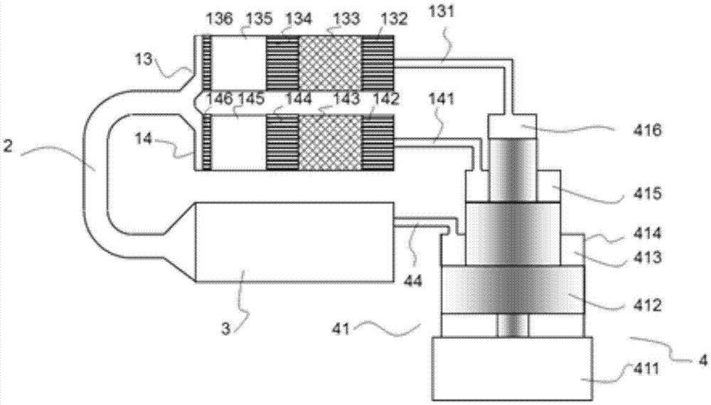
[0049] Such as image 3 As shown, in the parallel pulse tube refrigerator, two two-stage stepped compressors are replaced with a three-stage stepped compressor on the basis of Embodiment 1, so in this embodiment, the stepped compressor 41 has a compression chamber 415 And the compression chamber 416 and the expansion chamber 413, and the cold head 13 and the cold head 14 are driven by the compression chamber 415 and the compression chamber 416. The compression chamber 415 communicates with the cold head 14 through the first connecting pipe 141, and the compression chamber 416 passes through the first The connecting pipe 131 communicates with the cold head 13 .

[0050] All the other are with embodiment 1.


PUM


Abstract

The invention relates to a parallel type pulse tube machine. The parallel type pulse tube machine comprises compressors and a fixed part. The compressors are internally provided with n working cavities; the fixed part comprises an air reservoir, an inertia tube, a pulse tube, a first heat exchanger, a second heat exchanger and N heat regenerators parallelly arranged between the first heat exchanger and the second heat exchanger; and n and N are both integers larger than or equal to one. The two ends of each heat regenerator communicate with the working cavity of the common compressor; or, one end of each heat regenerator communicates with the working cavity of the corresponding compressor, and the other end of each heat regenerator communicates with the working cavity of the common compressor; or, one end of each heat regenerator communicates with the working cavity of the corresponding compressor, and the other end of each heat regenerator communicates with the working cavity of the another corresponding compressor. Compared with the prior art, the parallel type pulse tube machine is simple in integral structure, capable of being correspondingly expanded or shrunk according to the different working conditions, economical, practical and convenient to operate.

Description

technical field [0001] The invention belongs to the field of cryogenic refrigerators and relates to a parallel pulse tube machine. Background technique [0002] The pulse tube refrigerator was jointly proposed by Gifford and Longthworth in the United States in the 1960s, and has broad application prospects in aerospace, military and other aspects. The development of pulse tube refrigerators has gone through several stages of development, such as basic pulse tube refrigerators, small hole pulse tube refrigerators, and subsequent two-way inlet type, inertial tube type, four-valve type, and double-piston type pulse tube refrigerators. . Most of the pulse tube refrigerators currently in use are two-way inlet type, inertial tube type and a mixture of the two. [0003] However, whether it is a two-way inlet type or an inertial tube type pulse tube refrigerator, its expansion work cannot be recovered and dissipated in the inertial tube or gas store, which determines its theoretic...

Claims


Application Information

Patent Timeline
Patent Type & Authority Applications(China)
IPC IPC(8): F25B9/14
CPCF25B9/145F25B2309/1414
Inventor 朱绍伟
Owner TONGJI UNIV
Why Eureka
Try Eureka