an optical module

A technology of optical modules and lasers, applied in the field of optical modules

Active Publication Date: 2019-05-31
HISENSE BROADBAND MULTIMEDIA TECH
View PDF3 Cites 0 Cited by
  • Summary
  • Abstract
  • Description
  • Claims
  • Application Information

AI Technical Summary

Problems solved by technology

But in 25G or 100G products, the first spot diameter S 0 But 35um, the second spot diameter S 2 No more than 25um, at this time it is impossible to choose a S 0 value and S 2 value to meet the requirements of the above relationship

Method used


Image

  • an optical module
  • an optical module
  • an optical module

Examples


Embodiment Construction

[0020] In order to make the object, technical solution and advantages of the present invention clearer, the implementation manner of the present invention will be further described in detail below in conjunction with the accompanying drawings.

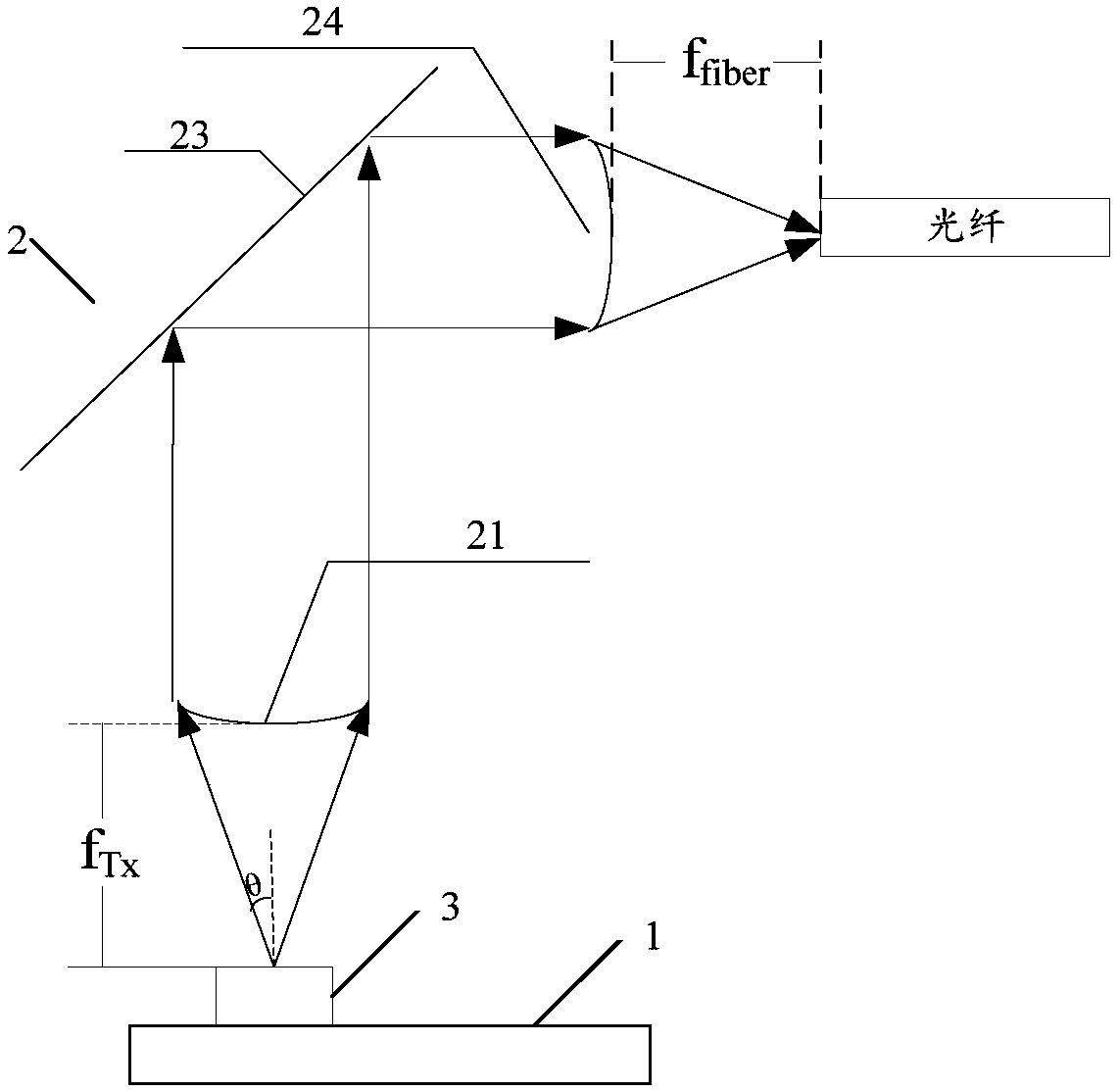
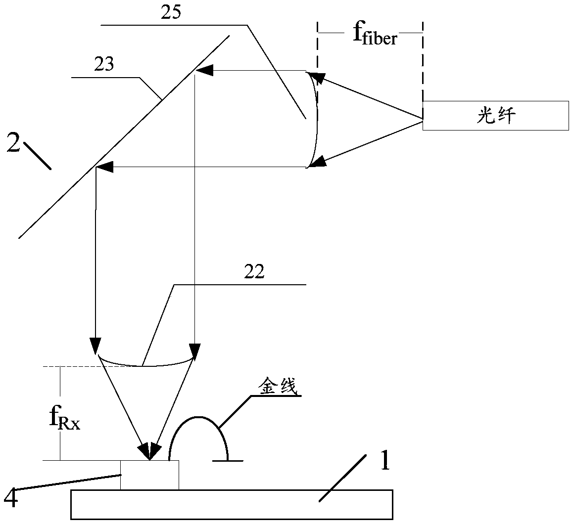
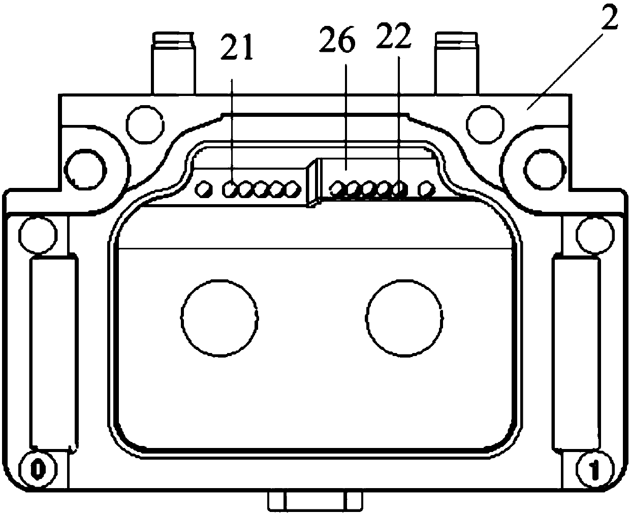
[0021] see figure 1 , figure 2 and image 3 , an embodiment of the present invention provides an optical module, including:

[0022] Circuit board 1, lens assembly 2, laser chip 3, light detection chip 4,

[0023] The laser chip 3 and the photodetection chip 4 are mounted on the surface of the circuit board 1 respectively;

[0024] The lens assembly 2 is covered above the laser chip 3 and the photodetection chip 4;

[0025] The lens assembly 2 has a transmitting lens 21, a receiving lens 22, a reflecting surface 23, a first fiber lens 24 and a second fiber lens 25;

[0026] The transmitting lens 21 and the receiving lens 22 have different focal lengths;

[0027] The first fiber lens 24 has the same focal length as the second fib...


PUM


Abstract

The invention discloses an optical module, which belongs to the communication field. The optical module includes: a circuit board, a lens assembly, a laser chip, and a photodetection chip. The laser chip and the photodetection chip are respectively mounted on the surface of the circuit board; the lens assembly is covered by the laser Above the chip and the light detection chip; the lens assembly has a transmitting lens, a receiving lens, a reflective surface, a first fiber optic lens and a second fiber optic lens; the transmitting lens and the receiving lens have different focal lengths; the The first optical fiber lens has the same focal length as the second optical fiber lens; the emitting lens emits the light emitted by the laser chip to the first optical fiber lens through the reflecting surface; the light from the second optical fiber lens passes through The reflective surface is then directed to the light detection chip through the receiving lens. The invention can meet the demands of different products.

Description

technical field [0001] The invention relates to the communication field, in particular to an optical module. Background technique [0002] The optical module has the functions of transmitting and receiving optical signals. The optical module includes optical components such as a laser and a detector. The laser can generate light, and the optical module converges the light into the first spot on the optical fiber and injects it into the optical fiber; the optical module also converges the light from the optical fiber on the detector. into a second light spot and enter the detector. [0003] The diameter S of the first light spot that the optical module converges on the optical fiber 0 , the laser emission size S 1 , the diameter S of the second light spot converged on the detector 2 And the diameter D of the optical fiber satisfies the following relationship: S 0 *S 2 = S 1 *D. Among them, the emission size S of the laser 1 Usually 20um, fiber diameter D is usually 5...

Claims


Application Information

Patent Timeline
Patent Type & Authority Patents(China)
IPC IPC(8): G02B6/42
CPCG02B6/4206G02B6/428G02B6/4286G02B6/4287G02B6/4296
Inventor 刘旭霞钟岩邵乾
Owner HISENSE BROADBAND MULTIMEDIA TECH
Why Eureka
Try Eureka