Light-path-equivalent light splitting prism group device with four split light beams

A beam splitting prism group, equal optical path technology, applied in optics, optical components, instruments, etc., can solve the problems of low spatial resolution, easy to produce errors, very sensitive phase shift errors, etc., to achieve high light energy utilization, high position Matching accuracy, high contrast effect

Inactive Publication Date: 2017-08-08
NANJING UNIV OF SCI & TECH
View PDF4 Cites 0 Cited by
  • Summary
  • Abstract
  • Description
  • Claims
  • Application Information

AI Technical Summary

Problems solved by technology

However, the prism in this device divides the incident light into four beams in the horizontal direction, and the shape of the detector is mostly a square or a rectangle close to a square, and the shape of the optical element is mostly circular, so the spatial resolution in many tests is relatively low. Low
And in this device, only three beams of light are used to reconstruct the phase using the three-step phase-shift method, which is very sensitive to phase-shift errors and is prone to errors

Method used


Image

  • Light-path-equivalent light splitting prism group device with four split light beams
  • Light-path-equivalent light splitting prism group device with four split light beams

Examples


Embodiment Construction

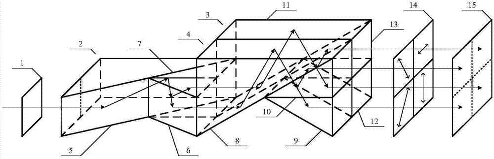
[0018] combine figure 1 , a four-beam beam-splitting equal optical path beam-splitting prism group device, comprising a λ / 4 wave plate 1, a first beam-splitting prism group 2, a second beam-splitting prism group 3, a third beam-splitting prism group 4 polarization array 14 and a detector 15 .

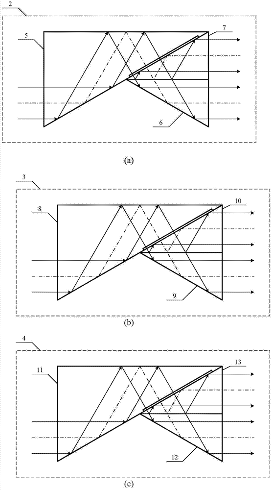
[0019] combine figure 1 and figure 2, the first dichroic prism group 2 includes a first triangular prism 5 , a second triangular prism 6 and a third triangular prism 7 . The second triangular prism 6 and the third triangular prism 7 are identical in shape and size, and the rectangular faces where the two long right-angled sides of the second triangular prism 6 and the third triangular prism 7 are close fit, and the rectangle where the two short right-angled sides are located The faces are coplanar, and the rectangular surface where the hypotenuse of the first triangular prism 5 is located has a groove near the side of the long right-angled side, and the rectangular surface where the...


PUM


Abstract

The invention discloses a light-path-equivalent light splitting prism group device with four split light beams. The prism group device comprises a lambda / 4 wave plate, three light splitting prism groups, a polarization array and a detector. Each light splitting prism group is formed by gluing three triangular prisms, and can divide one incident light beam into two beams of emergent light in equivalent light path. After that the three light splitting prism groups are combined, an orthogonal circularly polarized light beam which passes the lambda / 4 wave plate can be divided into four identical light beams, and via phase shift by the polarization array, four interference images are formed in the detector. Thus, the light splitting prism groups of special design is used to split the incident light in equivalent light path, and the utilization rate of light energy is very high. The four beams of emergent light are all parallel with the optical axis, and need not to be collimated by other optical components, and thus, the position matching precision is very high.

Description

technical field [0001] The invention relates to the field of optical interferometric measurement and testing, in particular to a four-beam beam-splitting equal optical path beam-splitting prism group device. Background technique [0002] Phase-shifting interferometry technology refers to a measurement technique that produces phase shifting through the modulation of the interference field, and then uses a certain algorithm to restore the physical quantity to be measured by using a certain algorithm from the collected phase-shifting interference images. Using phase-shifting technology, the phase can be restored by simple point-to-point calculations between interferograms. There is no need to locate the center of the fringe, and there is no need to use algorithms such as interpolation to fit the phase. Therefore, the phase-shifting interferometry technology significantly improves the accuracy and automation of interferometry. degree. Phase shifting methods can be divided into ...

Claims


Application Information

Patent Timeline
IPC IPC(8): G02B27/10G02B27/28
CPCG02B27/106G02B27/286
Inventor 周翔张辉钦郭仁慧蒋超郑东晖陈磊李建欣何勇
Owner NANJING UNIV OF SCI & TECH
Why Eureka
Try Eureka