Switch cabinet having dust removing function

A switchgear, functional technology

Inactive Publication Date: 2017-08-08
合肥易美特建材有限公司
View PDF5 Cites 9 Cited by
  • Summary
  • Abstract
  • Description
  • Claims
  • Application Information

AI Technical Summary

Problems solved by technology

[0004] However, operating experience shows that manual cleaning has a certain risk of electric shock, and operators may cause electric shock accidents due to opening the wrong cabinet door, and serious injuries may also result
These problems have brought some confusion to the operation and maintenance of the switchgear. On the one hand, cleaning the internal and external insulation equipment of the switchgear requires a power outage to the equipment, which reduces the reliability of the power supply; on the other hand, cleaning each switchgear requires a lot of Human resources, and there is a risk of electric shock

Method used


Image

  • Switch cabinet having dust removing function
  • Switch cabinet having dust removing function
  • Switch cabinet having dust removing function

Examples


Embodiment 1

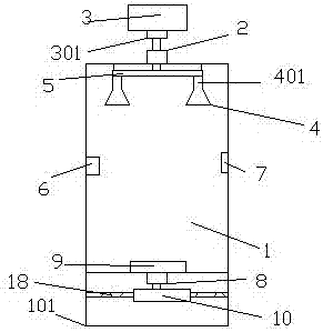
[0026] see figure 1 , this embodiment relates to a switch cabinet with a dust removal function, including a cabinet body 1, the cabinet body 1 is arranged on a base 101, an outlet-2 is provided on the top of the cabinet body 1, and an empty space is provided above the outlet-2. Compressor 3, the inner wall of the cabinet body 1 is provided with a plurality of nozzles 4, the air inlet 401 of the nozzle 4 is connected to the air outlet 301 of the air compressor 3 through the pipeline 5 passing through the outlet one 2, the The inside of the cabinet body 1 is provided with a dust monitoring device 6 and a controller 7, the bottom of the cabinet body 1 is provided with an outlet 2 8, and the upper part of the outlet 8 is provided with a vacuum cleaner 9, and the vacuum cleaner 9 passes through the pipeline 5 passing through the outlet 2 8 It is connected to the dust storage box 10 located below the outlet 2 8, and the controller 7 is respectively connected to the air compressor 3,...

Embodiment 2

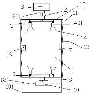
[0030] see figure 2 , this embodiment relates to a switch cabinet with a dust removal function, including a cabinet body 1, the cabinet body 1 is arranged on a base 101, and the top of the cabinet body 1 is provided with an outlet-2, and the outlet-2 An air compressor 3 is arranged above, and a plurality of nozzles 4 are arranged on the inner wall of the cabinet 1, and the air inlet 401 of the nozzle 4 and the air outlet 301 of the air compressor 3 pass through the pipeline 5 passing through the outlet one 2 connected, the inside of the cabinet 1 is provided with a dust monitoring device 6 and a controller 7, the bottom of the cabinet 1 is provided with an outlet 2 8, and the upper part of the outlet 8 is provided with a vacuum cleaner 9, and the vacuum cleaner 9 passes through the outlet 2 The pipeline 5 of 8 is connected to the dust storage box 10 located below the outlet 2 8, and the controller 7 is respectively connected to the air compressor 3, the dust monitoring device...

Embodiment 3

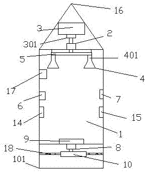
[0040] see image 3 , this embodiment relates to a switch cabinet with a dust removal function, including a cabinet body 1, the cabinet body 1 is arranged on a base 101, and the top of the cabinet body 1 is provided with an outlet-2, and the outlet-2 An air compressor 3 is arranged above, and a plurality of nozzles 4 are arranged on the inner wall of the cabinet 1, and the air inlet 401 of the nozzle 4 and the air outlet 301 of the air compressor 3 pass through the pipeline 5 passing through the outlet one 2 connected, the inside of the cabinet 1 is provided with a dust monitoring device 6 and a controller 7, the bottom of the cabinet 1 is provided with an outlet 2 8, and the upper part of the outlet 8 is provided with a vacuum cleaner 9, and the vacuum cleaner 9 passes through the outlet 2 The pipeline 5 of 8 is connected to the dust storage box 10 located below the outlet 2 8, and the controller 7 is respectively connected to the air compressor 3, the dust monitoring device ...


PUM


Abstract

The invention discloses a switch cabinet with a dust removal function, which comprises a cabinet body, the cabinet body is arranged on a base, an outlet 1 is arranged on the top of the cabinet body, an air compressor is arranged above the outlet 1, and an air compressor is arranged in the cabinet body. The wall is provided with a plurality of nozzles, and the air inlet of the nozzle is connected with the air outlet of the air compressor through a pipe passing through the outlet one, and a dust monitoring device and a controller are arranged inside the cabinet, and the cabinet body There is an outlet 2 at the bottom, and a vacuum cleaner is provided on the upper part of the outlet 2. The vacuum cleaner is connected to the dust storage box located below the outlet 2 through a pipe passing through the outlet 2. The controller is connected to the air compressor, the dust monitoring device and the vacuum cleaner respectively. Communication connected. The switchgear with dust removal function. The switchgear with dust removal function can independently complete the dust removal function, which enhances the reliability of power supply, reduces labor intensity, and ensures the personal safety of staff.

Description

technical field [0001] The invention relates to the technical field of switch cabinets, in particular to a switch cabinet with a dust removal function. Background technique [0002] The switch cabinet is a kind of electrical equipment. The outside line of the switch cabinet first enters the main control switch in the cabinet, and then enters the sub-control switch. Each branch is set according to its needs. Such as instruments, automatic controls, motor magnetic switches, various AC contactors, etc., some also have high-voltage room and low-voltage room switch cabinets, high-voltage busbars, such as power plants, etc. load shedding. [0003] Switchgear has been widely used in my country's power system. Because it is not an absolutely airtight system, due to factors such as natural settlement and electric field force, the surface of its internal equipment will be polluted, and the degree of pollution will increase with the increase of operating time. Therefore, it is necessa...

Claims


Application Information

Patent Timeline
Patent Type & Authority Applications(China)
IPC IPC(8): H02B1/28B08B5/02B08B5/04B08B15/04B08B17/04B08B13/00
CPCH02B1/28B08B5/02B08B5/04B08B13/00B08B15/04B08B17/04
Inventor 朱明静
Owner 合肥易美特建材有限公司
Why Eureka
Try Eureka