
Charging device and charging method

A charging equipment and equipment technology, applied in the electrical field, can solve the problems of single function, limited use site, difficult to move, etc., to achieve the effect of wide application scene, prevent clutter, and reduce service life

Pending Publication Date: 2017-08-08
杭州小电科技股份有限公司
View PDF3 Cites 10 Cited by
  • Summary
  • Abstract
  • Description
  • Claims
  • Application Information

AI Technical Summary

Problems solved by technology

[0003] With the improvement of social informatization, mobile electronic devices such as mobile phones and tablet computers have become indispensable items when going out, but due to the size of mobile electronic devices and the development of battery technology, they cannot provide long-term battery life, thus It is necessary to carry mobile power storage equipment (such as charging treasure) or find fixed charging devices (such as mobile phone charging piles) in public places to supplement power for mobile electronic devices, but the above two power supply equipment have their own defects: mobile power storage equipment It must be carried by the user and used in a small area and cannot provide unspecified users with a paid function in the public domain; the fixed charging device is too large and not easy to move, which has great restrictions on the use site
In addition to the above shortcomings, the existing power supply equipment also has other shortcomings such as single function, messy charging lines and insufficient strength, unclear charging instructions, etc.

Method used


Image

  • Charging device and charging method
  • Charging device and charging method
  • Charging device and charging method

Examples


Embodiment 1

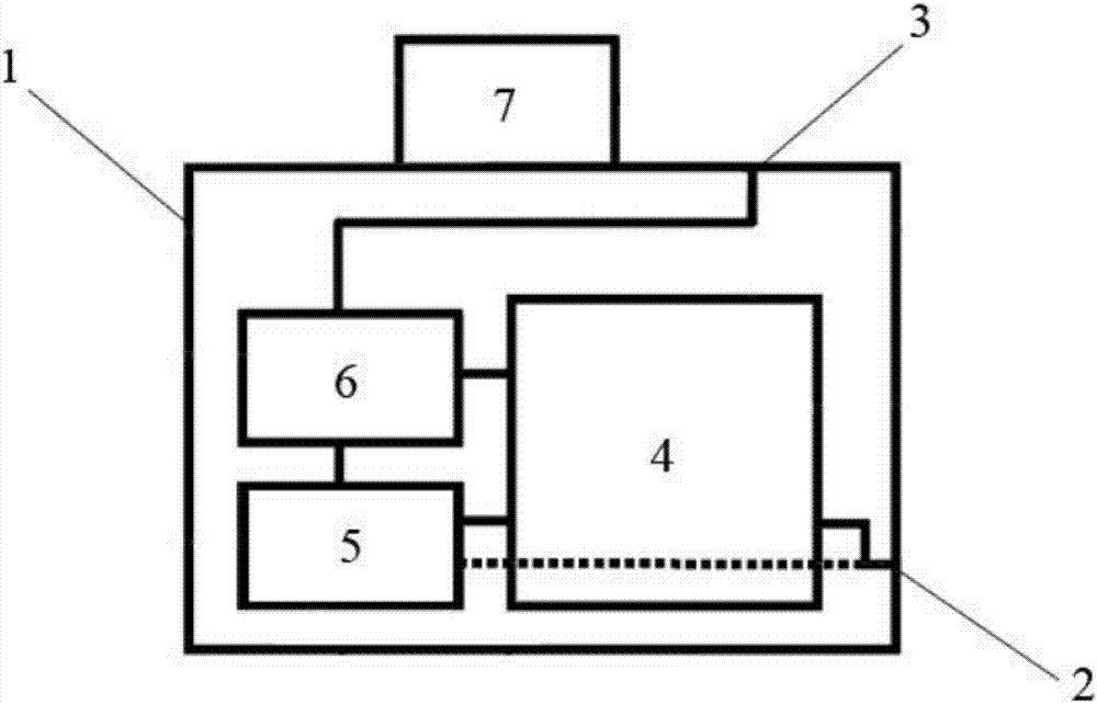
[0032] Such as figure 1, this embodiment includes a main body 1, a power input end 2 and a power output end 3, the main body 1 is provided with a power storage device 4, a communication device 5, a controller 6 and an equipment identification 7, and the power input end 2 is connected to the power storage device 4 , wherein the power storage device 4 is a detachable battery. When the power storage device 4 is disassembled from the main body 1, the power input terminal 2 is directly connected to the communication device 5, the controller 6 and the power output terminal 3 through an external power supply (not shown in the figure). Power supply; when the power storage device 4 is installed on the main body 1, if the equipment main body 1 is connected to an external power supply, the external power supply is also charging the power storage device 4 while supplying power to the communication device 5, the controller 6 and the power output terminal 3, And if the device main body 1 is...

Embodiment 2

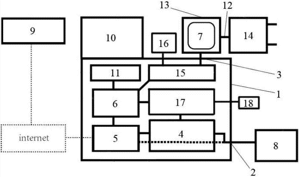
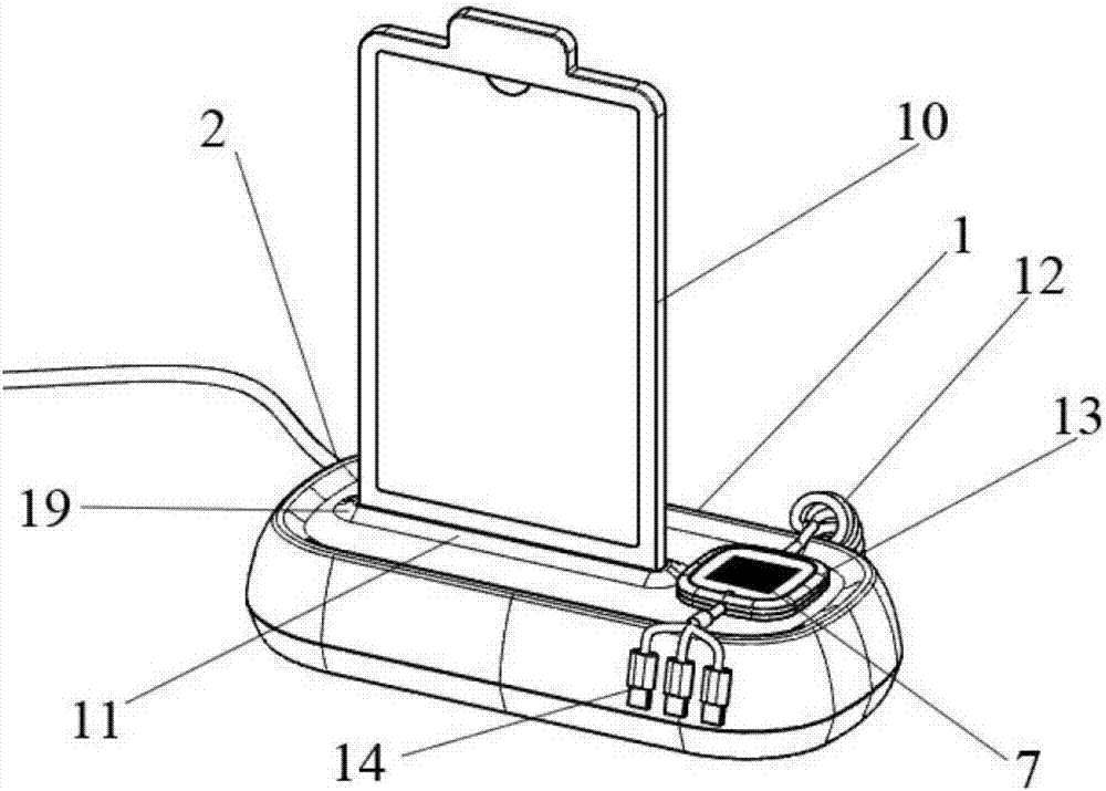
[0034] Such as figure 2 As shown, this embodiment includes a main body 1, a power input terminal 2 and a power output terminal 3. The main body 1 is provided with a power storage device 4, a communication device 5, a controller 6, an equipment identification 7, an external identification 10 and a lighting device 11. The power input terminal 2 is connected with the power storage device 4, if the device main body 1 is connected to the external power supply 8, the external power supply 8 is also charging the power storage device 4 while supplying power to the communication device 5, the controller 6 and the power output terminal 3, and If the device main body 1 is not connected to the external power supply 8 , the power storage device 4 directly supplies power to the communication device 5 , the controller 6 and the power output terminal 3 . The communication device 5, the power output terminal 3 and the lighting device 11 (such as an LED lamp) are connected to the controller 6,...

Embodiment 3

[0036] Such as figure 2 As shown, on the basis of Embodiment 2, the present embodiment adds a charging line 12, an identification seat 13, a charging head 14, a timer 15, a display screen 16, a power detection device 17 and an indicator 18, wherein the charging line 12 is connected to a power supply The output terminal 3 and the charging line 12 are provided with an identification seat 13, and the device identification 7 is arranged on the identification seat 13, and the identification seat 13 is detachable from the main body 1 through a slot, a limit block, a fastener, friction force or magnetic force, etc. The other end of the charging cable 12 is provided with a charging head 14 for positioning cooperation. The timer 15 is connected with the controller 6 for controlling the remaining charging time. The timer 15 includes a display screen 16 which is arranged outside the main body 1 and is used for displaying the remaining charging time. The power detection device 17 is con...


PUM


Abstract

The invention relates to a charging device and a charging method. The charging device includes a main body, a power supply input end and a power supply output end. The charging device is characterized in that the main body is provided with a power supply storage apparatus, a communication apparatus, a controller and a device marker. The power supply input end is connected to the power supply storage apparatus. The power supply input end or the power supply storage apparatus supplies power to the communication apparatus, the controller and the power output end. The communication apparatus and the power supply output is connected to the controller. The device marker corresponds to the charging device of a mobile phone. The charging device can be used as pay charging device in public venues, is not limited by venues, can combine with demonstration function in specific venue and is portable.

Description

[0001] The present invention claims the priority of a Chinese patent application filed with the China Patent Office on January 3, 2017, with the application number 201720003151.1 and the title of the invention "a multifunctional mobile self-service charging device for mobile phones", the entire contents of which are incorporated by reference in this application. technical field [0002] The invention relates to the field of electrical technology, in particular to a charging device and a charging method. Background technique [0003] With the improvement of social informatization, mobile electronic devices such as mobile phones and tablet computers have become indispensable items when going out, but due to the size of mobile electronic devices and the development of battery technology, they cannot provide long-term battery life, thus It is necessary to carry mobile power storage equipment (such as charging treasure) or find fixed charging devices (such as mobile phone chargin...

Claims


Application Information

Patent Timeline
IPC IPC(8): H02J7/00
CPCH02J7/0027H02J7/0047H02J7/00043H02J7/0048Y02T90/12
Inventor 李向东黄巧玲
Owner 杭州小电科技股份有限公司
Learn More