AI technical title is built by Patsnap AI team. It summarizes the technical point description of the patent document.
A compound machining and cutting tool technology, applied in milling cutters, manufacturing tools, drilling tool accessories, etc., can solve the problems of unsuitable processing of blind holes and long drilling parts, and achieves improvement of cutting efficiency, suppression of delamination, and increase of diameter. effect on the component
Active Publication Date: 2019-01-25
ZHUZHOU CEMENTED CARBIDE CUTTING TOOLS CO LTD
View PDF3 Cites 0 Cited by
Summary
Abstract
Description
Claims
Application Information
AI Technical Summary
This helps you quickly interpret patents by identifying the three key elements:
Problems solved by technology
Method used
Benefits of technology
Problems solved by technology
Yet the first apex angle of this invention is 60 °~80 °, and the taper transition area angle is 2 °~8 °, and the taper angle of apex angle and transition area is all designed less, makes drilling position very long, and drill bit is not It is suitable for processing blind holes on thick parts, and when processing through holes, it is also required that there must be enough space at the exit of the hole to allow the drill tip to drill out
Method used
Image
Click on the blue label to locate the original text in one second.
Reading with bidirectional positioning of images and text.
Examples
Embodiment 1
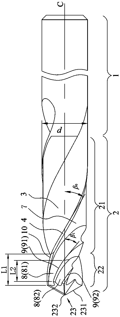
[0028] Such as Figure 1 to Figure 3 As shown, the milling and drilling compound processing tool (twist drill) of the present embodiment includes a cutter body 2 and a handle 1, and the cutter body 2 includes a drilling part 23, a milling part 22 and a guide part 21 arranged in sequence, and the guide part 21 and the guide part 21 are arranged in sequence. The tool holder is connected, the drilling part 23 is located at the front end of the milling part 22, the milling part 22 has a certain taper, the guide part 21 includes at least two long spiral chip flutes 3 extending from the drilling part 23 to the tool handle 1, and the cutter body 2 The part between two adjacent long spiral chip flutes 3 constitutes a blade 7, and the blade 7 is provided with a cylindrical guide land 4 (that is, the blade 7) A cylindrical guide land 4) is set on the edge of the side that first enters into the rotation, and the milling part 22 intersects with the side of the long spiral chip flute 3 fac...
Embodiment 2
[0038] Such as Figure 4 and 5 As shown, this embodiment is basically the same as Embodiment 1, the only difference is that in this embodiment, there are two long helical chip removal flutes 3 and two short helical chip removal flutes 8, that is, each blade 7 Set 1 above.
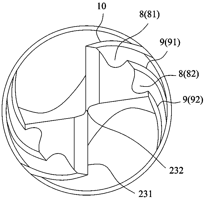
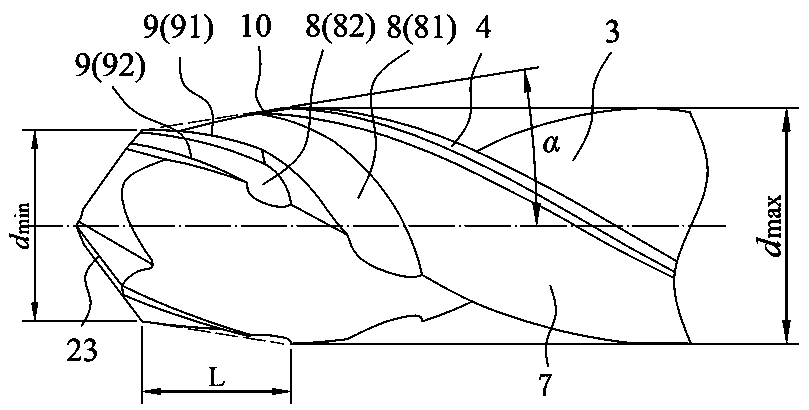
[0039] This embodiment is suitable for a twist drill with a small tool diameter and a small width of the blade 7 . The drilling portion 23 includes two main drilling edges 231 and a chisel edge 232 . In the present embodiment, each design parameter is respectively α=10°, β 1 = 33°, β 0 = 30°, d=10mm, d min = 0.76d, L=6.8mm, L1=6.8mm, L2=4.6mm.
Embodiment 3
[0041] Such as Figure 6 and 7 As shown, this embodiment is basically the same as Embodiment 1, the only difference is that in this embodiment, the number of long helical chip removal flutes 3 is set to three, and the number of short helical chip removal flutes 8 is set to three, that is, each blade 7 Set 1 above.
[0042] This embodiment is suitable for a three-blade twist drill, and the drilling part 23 includes three main drilling edges 231 and three chisel edges 232, and the design parameters are: α = 10°, β 1 = 33°, β 0 = 35°, d=10mm, d min = 0.76d, L=6.8mm, L1=6.8mm, L2=4.6mm.
PUM
Abstract
The invention discloses a milling and drilling combined machining cutter. The milling and drilling combined machining cutter comprises a cutter body and a cutter handle; the cutter body comprises a drilling part, a milling part and a guide part which are arranged in sequence; the guide part is connected with the cutter handle; the drilling part is positioned at the front end of the milling part; the milling part has certain conicity; the guide part comprises at least two long helical chip discharging grooves which extend from the drilling part to the cutter handle; a part, positioned between two adjacent long helical chip discharging grooves, of the cutter body forms a blade petal; the side surface, close to the long helical chip discharging grooves and opposite to the rotating direction of the cutter body, of the blade petal is provided with a cylindrical guide blade strip; the side surface, opposite to the rotating direction of the cutter body, of each long helical chip discharging groove is intersected with the milling part to form a taper long milling blade; the blade petal is provided with at least one short helical chip discharging groove which extends from the milling part to the guide part; and the milling part is intersected with the side surface, opposite to the rotating direction of the cutter body, of each short helical chip discharging groove to form a taper short milling blade. Under a composite material drilling machining condition, the milling and drilling combined machining cutter disclosed by the invention can reduce an axial cutting force so as to prevent defects of layering, cracks and burrs generated at the outlet of a machined hole.
Description
technical field [0001] The invention relates to the field of composite material cutting, in particular to a milling and drilling composite processing tool. Background technique [0002] Composite materials have a series of advantages such as high specific strength, large specific modulus, fatigue resistance, and corrosion resistance. At present, the application prospects in the aerospace field are very broad, especially fiber reinforced composites (FRP), which are widely used in aircraft wings. and tail rudder. The wings and tail rudder need to process thousands of riveting or screwing holes because they need to be assembled and connected with the aircraft fuselage. Due to the particularity of the fiber composite manufacturing process, its mechanical properties are anisotropic, and the interlayer strength is low. During the process of drilling riveted or screwed holes, defects such as delamination and tearing are prone to occur due to the action of axial cutting force. , w...
Claims
Application Information
Patent Timeline
Application Date:The date an application was filed.
Publication Date:The date a patent or application was officially published.
First Publication Date:The earliest publication date of a patent with the same application number.
Issue Date:Publication date of the patent grant document.
PCT Entry Date:The Entry date of PCT National Phase.
Estimated Expiry Date:The statutory expiry date of a patent right according to the Patent Law, and it is the longest term of protection that the patent right can achieve without the termination of the patent right due to other reasons(Term extension factor has been taken into account ).
Invalid Date:Actual expiry date is based on effective date or publication date of legal transaction data of invalid patent.
Patent Type & AuthorityPatents(China)
IPC IPC(8): B23B51/08B23C5/10
CPCB23B51/08B23C5/1018
Inventor曾滔邓小野李蓉肖跃勇
OwnerZHUZHOU CEMENTED CARBIDE CUTTING TOOLS CO LTD

