Vibration forming mold as well as pressure head assembly and pressure head thereof

A technology of indenters and components, applied in manufacturing tools, metal processing equipment, grinding devices, etc., can solve problems such as poor quality of grinding wheels, and achieve the effects of uniform distribution, improved flow performance, and dense powder.

Active Publication Date: 2017-08-11
ZHENGZHOU RES INST FOR ABRASIVES & GRINDING CO LTD
View PDF12 Cites 0 Cited by
  • Summary
  • Abstract
  • Description
  • Claims
  • Application Information

AI Technical Summary

Problems solved by technology

[0005] The object of the present invention is to provide a kind of vibrating forming mold to solve the problem of poor quality of the grinding wheel manufactured by using the forming die in the prior art;

Method used


Image

  • Vibration forming mold as well as pressure head assembly and pressure head thereof
  • Vibration forming mold as well as pressure head assembly and pressure head thereof
  • Vibration forming mold as well as pressure head assembly and pressure head thereof

Examples


Embodiment 2

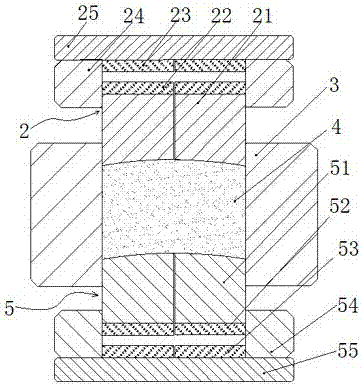
[0044] Embodiment 2 of the vibration forming mold of the present invention: the difference from Embodiment 1 is only that the arrangement of each sub-indenter in the upper and lower indenter bodies is different, and the specific structure of the upper indenter body 21 is as follows Figure 5 As shown, the gaps between the eight upper sub-indenters 211 extend along the axial direction of the indenters, and a plurality of gaps are arranged at intervals along the circumference of the indenters.

Embodiment 3

[0045] Embodiment 3 of the vibration forming mold of the present invention: the difference from Embodiment 1 is only that the arrangement of each sub-indenter in the upper and lower indenter bodies is different, and the specific structure of the upper indenter body 21 is as follows Figure 6 As shown, the gaps between the 8 upper sub-indenters 211 intersect with the axial direction of the indenters obliquely. Specifically, the gaps between the upper sub-indenters 211 and the axial direction of the indenters form an angle of 135 degrees. The gap between the heads is at an angle of 45 degrees to the axial direction of the indenter. The form in which the gaps between the sub-indenters obliquely intersect with the axis of the indenters is conducive to smooth transition of the pressing surface of the abrasive block surrounded by the plurality of sub-indenters, and is beneficial to reducing vibration during the grinding process.

Embodiment 4

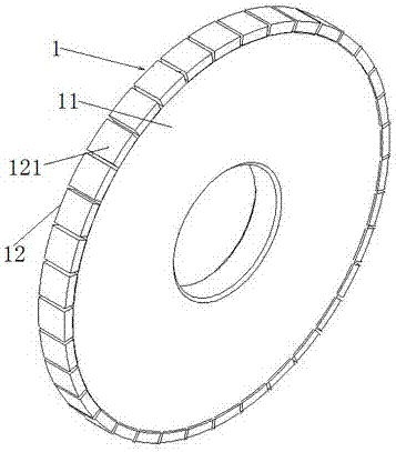
[0046] Embodiment 4 of the vibration molding mold of the present invention: the difference from Embodiment 1 is that the abrasive block to be prepared is an integral ring-shaped abrasive ring, and the mold sleeve accordingly includes an outer cylinder 32 and an inner cylinder coaxially sleeved 31. The annular gap between the inner cylinder 31 and the outer cylinder 32 forms a through hole for inserting the upper and lower pressure head bodies. At this time, the upper and lower indenter bodies are all made up of three ring-shaped sub-indenters in turn, and the electromagnet and magnet are also annular rings that match the shape and size of the corresponding sub-indenters. Correspondingly prepared abrasive ring 12 is also a ring with imaginary part 123 and real part 122 alternated. The specific structure of the grinding tool and the prepared abrasive ring is as follows: Figure 7 and Figure 8 shown.

[0047] In other embodiments: the indenter body can also be an integral stru...


PUM


Abstract

The invention relates to a vibration forming mold as well as a pressure head assembly and a pressure head thereof, and aims to solve the problem that abrasive wheels manufactured by a vibration forming mold in the prior art are poor in quality. When the pressure head disclosed by the invention is used, a vibrating mechanism between the pressure head seat and the pressure head body is controlled to generate the vibration in an up-down direction, so that the pressure head body can be driven to vibrate in the up-down direction; and the flowing property of powder in a mold cavity is improved through the vibration of the pressure head body, so that the distribution of the powder in the mold cavity is more uniform, and obtaining a material grinding block of which the inner part density is uniform and the abrasive wheels which are good in properties is facilitated.

Description

technical field [0001] The invention relates to a vibration forming mold, a pressure head assembly and a pressure head thereof. Background technique [0002] The structure of superhard material grinding wheel 1 is as figure 1 As shown, it usually consists of two parts: a substrate 11 and an abrasive layer 12. The substrate 11 is usually a disk-shaped part made of metal material, and the abrasive layer 12 is a working layer that directly participates in the grinding process. For the large-diameter superhard material emery wheel 1, since the preparation of the overall abrasive layer is difficult, the abrasive layer 12 is often separated along its circumferential direction to form a plurality of abrasive blocks 121, and each abrasive block 121 is pressed separately. The pressed abrasive block 121 is processed in a subsequent special process to form a grinding wheel block, and the prepared grinding wheel block is bonded and fixed on the outer peripheral surface of the base body...

Claims


Application Information

Patent Timeline
IPC IPC(8): B24D18/00
CPCB24D18/0009
Inventor 邢波吴晓磊
Owner ZHENGZHOU RES INST FOR ABRASIVES & GRINDING CO LTD
Why Eureka
Try Eureka