Air blowing and mud collecting type air floatation tank

A flotation tank and sludge collection technology, which is applied in flotation water/sewage treatment, energy waste water treatment, flocculation/sedimentation water/sewage treatment, etc., can solve the problems of affecting filtration steps, long residence time, and increased sludge content. Achieve the effect of speeding up the reaction speed, improving the utilization rate and reducing the mud content

Active Publication Date: 2017-08-11
新疆中泰创新技术研究院有限责任公司
View PDF5 Cites 4 Cited by
  • Summary
  • Abstract
  • Description
  • Claims
  • Application Information

AI Technical Summary

Problems solved by technology

[0004] Although the development of air flotation and dissolved air equipment and slag scraping machine is very mature, there are still some minor problems in the whole air flotation step, such as during the dosing reaction, because the water flow is in a flowing state during the whole process of the air flotation step, Therefore, there are generally phenomena of uneven reaction and low utilization rate of coagulant. For example, the scum directly below the slag guide plate is difficult to be scraped away by the slag scraper. Clean away, stay for a long time, easy to disintegrate, form sediment, affect the quality of clear water, increase the mud content, affect the subsequent filtration steps, more scum will penetrate the filter layer, and the filter layer will lose its filtering effect, so it is urgent Need to invent a kind of air flotation pool, to solve the above problems

Method used


Image

  • Air blowing and mud collecting type air floatation tank
  • Air blowing and mud collecting type air floatation tank

Examples


Embodiment Construction

[0033] The present invention will be further described in detail below in conjunction with the accompanying drawings, so that those skilled in the art can implement it with reference to the description.

[0034] In the description of the present invention, the orientations or positional relationships indicated by the terms "transverse", "upper", "lower", "top", "bottom", "inner", "outer" etc. are based on the orientations shown in the drawings Or positional relationship is only for the convenience of describing the present invention and simplifying the description, and does not indicate or imply that the referred device or element must have a specific orientation, be constructed and operated in a specific orientation, and therefore should not be construed as a limitation of the present invention.

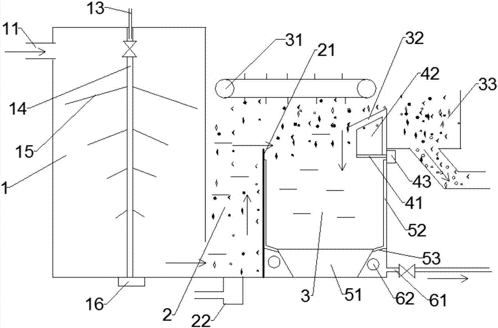
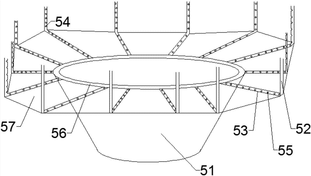
[0035] like Figure 1~2 Shown, the present invention provides a kind of air blowing mud collection type air flotation tank, comprising:

[0036] Reaction tank 1, its upper end is p...


PUM

PropertyMeasurementUnit
pore sizeaaaaaaaaaa
lengthaaaaaaaaaa
widthaaaaaaaaaa

Abstract

The invention discloses an air blowing and mud collecting type air floatation tank. The air blowing and mud collecting type air floatation tank comprises a reaction tank and a contact separation tank, wherein the reaction tank comprises an agent guiding device, the agent guiding device comprises a main vertically arranged pipe, multiple groups of branch pipes fixed to the outer side wall of the main pipe at intervals from top to bottom and a first motor driving the main pipe to rotate, the lengths of the multiple groups of branch pipes are decrease sequentially and progressively from top to bottom, and multiple agent outlet holes are uniformly formed in the multiple groups of branch pipes and the main pipe. The contact separation tank is located at the downstream of the reaction tank, the lower side of the contact separation tank is communicated with the reaction tank, a partition plate is vertically arranged in the contact separation tank and divides the contact separation tank into an upstream contact zone and a downstream separation zone, and the separation zone comprises a residue removal component, a swing component, an air blowing and mud collecting component and a water outlet component. The air blowing and mud collecting type air floatation tank has the advantages of accelerating coagulant and raw water reaction, improving the coagulant utilization rate, removing floating residues at the dead corner position of a residue guiding plate and at the position below the separation zone in time, collecting the floating residues decomposed into sinking mud in a centralized mode, greatly decreasing the mud content of clear water and ensuring the quality of outlet clear water.

Description

technical field [0001] The invention relates to the field of sewage treatment. More specifically, the present invention relates to an air blowing mud collection type air flotation tank. Background technique [0002] Sewage treatment technology mainly includes the following steps, pretreatment, coagulation and sedimentation, flotation and air flotation, filtration, redox, activated carbon adsorption, and membrane separation. Among them, flotation is mainly treated by natural flotation devices to separate substances with a specific gravity lower than water, such as oil. , and the substance with a specific gravity greater than water is processed by an air flotation device. The principle is that the fine air bubbles first adhere to the suspended particles in the water to form a "bubble-particle" complex with an overall density lower than that of water, so that the suspended particles float together with the air bubbles. Raise to the surface of the water, and then scrape off the...

Claims


Application Information

Patent Timeline
Patent Type & Authority Applications(China)
IPC IPC(8): C02F1/24C02F1/52
CPCC02F1/24C02F1/52Y02W10/33
Inventor 韦爱龄
Owner 新疆中泰创新技术研究院有限责任公司
Why Eureka
Try Eureka