
Simulation candle

A technology for simulating candles and flame hoods, applied in the field of simulating candles, can solve the problems of not being natural and realistic enough, and achieve the effect of natural and lifelike flame swings with large amplitude

Inactive Publication Date: 2017-08-11
NINGBO CREATED ELECTRONICS
View PDF6 Cites 11 Cited by
  • Summary
  • Abstract
  • Description
  • Claims
  • Application Information

AI Technical Summary

Problems solved by technology

The existing simulated candle lamp is composed of a candle simulation shell, a flame simulation reflector, a light source, a steel wire support line and a swing driving mechanism of the flame simulation reflector. The reflector swings on the steel wire support line as the axis. Although it can obtain the effect of simulating the swing of the candle flame, it is not natural enough and needs to be improved.

Method used


Image

  • Simulation candle
  • Simulation candle
  • Simulation candle

Examples


Embodiment 1

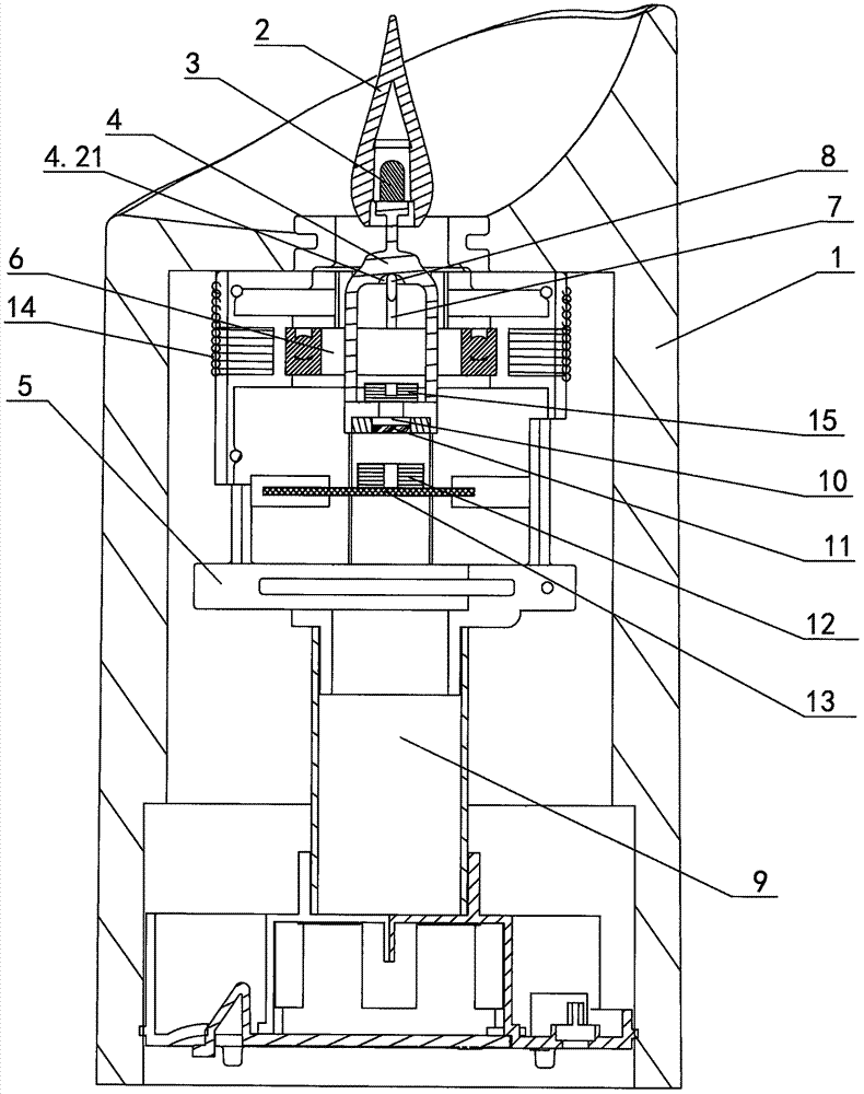
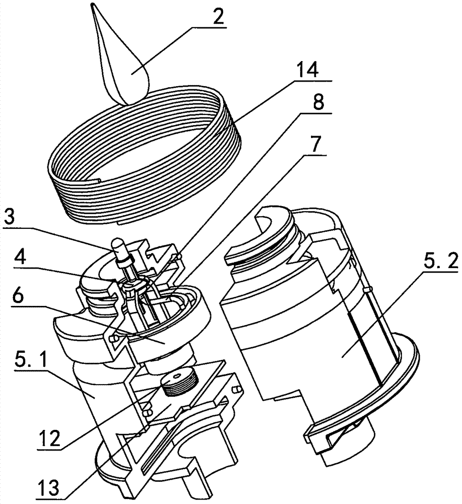
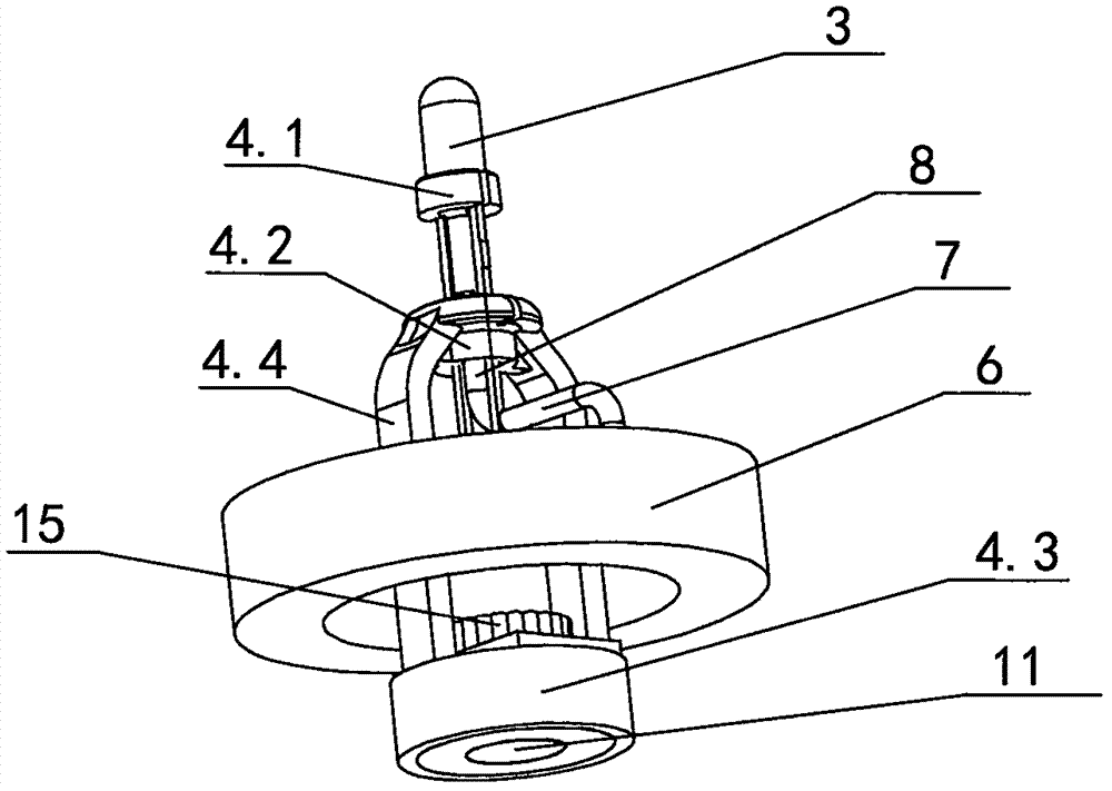
[0019] The artificial candle of present embodiment is as Figures 1 to 3 As shown, it includes a candle housing 1 , a flame cover 2 , a light source 3 , a swinging member 4 , a support frame 5 , a driving mechanism for driving the swinging member 4 and a power supply 9 . Among them, the candle shell 1 is made of paraffin; the flame cover 2 is a water drop shape made of milky white acrylic, the upper part is a conical flame tip, and the lower part is a hollow hemispherical flame body. The flame cover 2 can also be made of other light-transmitting materials. The light source 3 adopts a milky white or yellow LED lamp, and the LED lamp head is arranged in a hemispherical flame body cavity. The induction coil 15 corresponds to the electromagnetic coil B14, and the electromagnetic coil B14 is electrically connected to the power supply 9; the pendulum 4 is a hollow pendulum composed of an upper pendulum and a lower hammer body 4.3. The lamp holder 4.1 at the upper end is fixed, and ...

Embodiment 2

[0022] The artificial candle of present embodiment is as Figure 4 with 5 As shown, the structure of the simulated candle is basically the same as that of Embodiment 1, and a fulcrum 8 is also provided, so that the pendulum swings at 360° at a fulcrum where the fulcrum hole 4.21 contacts the fulcrum 8; the difference is that in this embodiment The simulation candle in the first is that the bearing 6 is not provided, and the support rod 7 of the support shaft 8 is fixedly connected with the inner wall of the bracket 5; the second is that the electromagnetic coil B14 and the magnetic induction coil 15 are not provided, and the electromagnetic coil A12 is installed on the drive circuit board 13 ', the light source 3 is electrically connected to the driving circuit board 13' through a wire (not shown in the figure), and the driving circuit board 13' is electrically connected to the power supply 9, and the light source 3 is controlled by the driving circuit board 13' to realize the...


PUM


Abstract

The invention discloses a simulation candle. A supporting part of the candle is a supporting shaft a supporting shaft hole is formed in a swing part, and the supporting shaft is sleeved with the supporting shaft hole. The candle has the beneficial effects that due to the adoption of the manner that the supporting shaft and the supporting shaft hole are matched, a flame cover fixed to the swing part swings in a supporting point manner, 360-degree swing can be achieved, and flame swing is more natural and vivid; preferably, the bottom end of the supporting shaft is fixed to the inner ring of a bearing mounted on a supporting frame through a supporting rod, a light source is electrically connected with a magneto-electric induction coil mounted on the swing part, an electromagnetic coil B corresponding to the magneto-electric induction coil is arranged on the supporting frame and is electrically connected with the power source, current generated by magneto-electric induction is used for supplying power to the light source, interference of pulling between the light source and a power source is reduced, the swing part can swing more freely, in the swing process of the swing part, the current generated by the magneto-electric induction is changed along with changes of the swing speed, and after the light source is powered on, the more natural light and dark changes can be formed.

Description

technical field [0001] The invention relates to a lighting device, in particular to an artificial candle. Background technique [0002] At present, in some specific occasions, in order to reduce fire hazards, reduce carbon dioxide emissions, and facilitate use, candles are usually no longer used, and artificial candle lights that resemble candles are used. The existing simulated candle lamp is composed of a candle simulation shell, a flame simulation reflector, a light source, a steel wire support line and a swing driving mechanism of the flame simulation reflector. The reflector swings on the steel wire support line as the axis. Although the effect of simulating the swing of the candle flame can be obtained, it is not natural enough and needs to be improved. Contents of the invention [0003] The technical problem to be solved by the invention is to provide an artificial candle with natural and lifelike flame swing. [0004] The technical solution adopted by the present...

Claims


Application Information

Patent Timeline
Patent Type & Authority Applications(China)
IPC IPC(8): F21S6/00F21S10/04F21V3/02F21V3/04F21V14/08F21V23/00F21Y115/10
CPCF21S6/001F21S10/046F21V3/02F21V3/062F21V14/08F21V23/003
Inventor 王立明
Owner NINGBO CREATED ELECTRONICS
Learn More