Wire diameter measurement special tool

A special tool and wire diameter technology, applied in the field of special tools for wire diameter measurement, to achieve the effects of easy portability, accurate data measurement, and improved work efficiency

Inactive Publication Date: 2017-08-11
国网新疆电力有限公司博尔塔拉供电公司 +1
View PDF9 Cites 4 Cited by
  • Summary
  • Abstract
  • Description
  • Claims
  • Application Information

AI Technical Summary

Problems solved by technology

[0004] The technical problem to be solved by the present invention is to measure the wire diameter under the condition of energizing and not working on heights, effectively avoiding some potential safety hazards caused by the type of the wire not meeting the requirements, and the angle can be adjusted to adapt to the measurement requirements in different environments. Accurate measurement data, greatly improving work efficiency

Method used


Image

  • Wire diameter measurement special tool
  • Wire diameter measurement special tool
  • Wire diameter measurement special tool

Examples


Embodiment 1

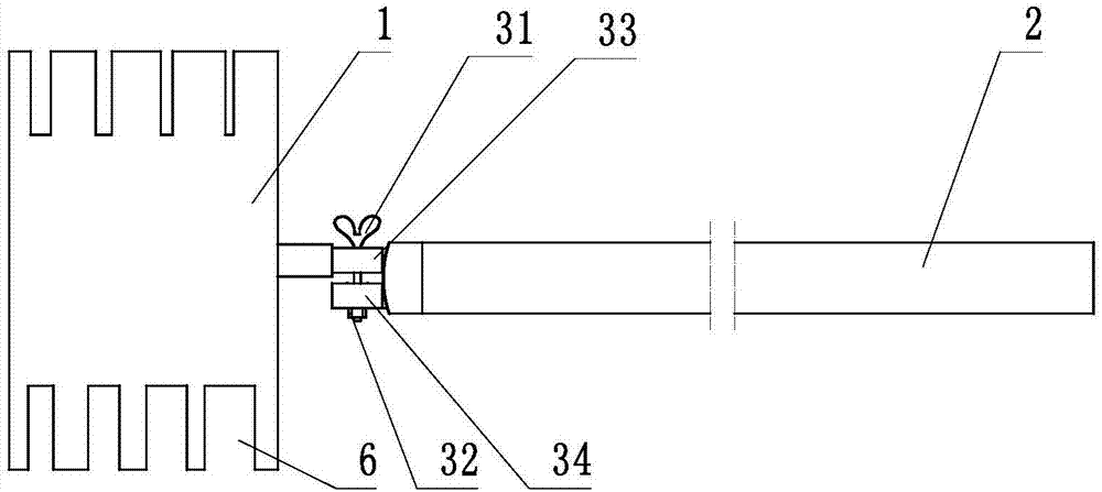
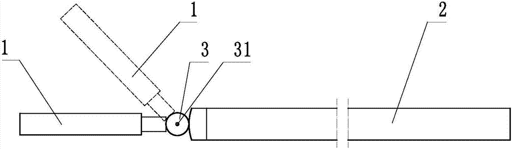
[0031] Embodiment 1: refer to Figure 1~2 , which is a structural schematic diagram of this embodiment, a special tool for measuring wire diameters, including a measuring board 1 and an insulating rod 2, the measuring board 1 is a plate-shaped structure and 2 to 10 measuring devices of different specifications are arranged at the edge Port 6, the measuring port 6 is a notch arranged on the edge of the measuring plate 1, the notch is in a "U" shape, that is, the opposite sides are parallel to each other, and the distance between the two opposite parallel sides of each measuring port 6 is different, One end of the insulating rod 2 is a free end, and the other end is connected with the measuring plate 1 through the adjusting mechanism 3, the measuring plate 1 and the adjusting mechanism 3 are welded, the insulating rod 2 is riveted with the adjusting mechanism 3, and the measuring The plate 1 and the insulating rod 2 can rotate relatively around the adjusting mechanism 3, the adj...

Embodiment 2

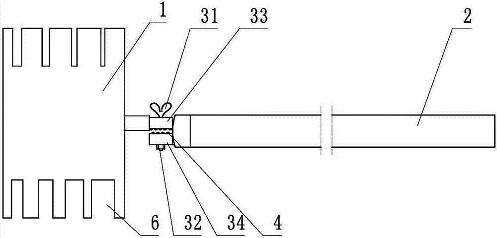
[0033] Embodiment 2: refer to image 3 , is a schematic diagram of the structure of Embodiment 2 of the present invention. Compared with Embodiment 1, the difference of this embodiment is that: the contact surfaces of the fastener A33 and the fastener B34 are provided with multiple sets of anti-skid protrusions that engage with each other 4, and the anti-slip protrusion 4 is arranged at the edge of the contact surface of the fastener A33 and the fastener B34, the anti-slip protrusion 4 is a cone structure, and the above-mentioned anti-slip protrusion 4 can prevent the fastener A33 and The relative movement of the part B34 ensures that the relative position of the measuring board 1 and the insulating rod 2 remains unchanged during the operation.

Embodiment 3

[0034] Embodiment 3: refer to Figure 4~5 , is a structural schematic diagram of Embodiment 3 of the present invention. Compared with any embodiment of Embodiments 1 to 2, the difference of this embodiment is that the insulating rod 2 can be stretched, and the specific structure is as follows: the insulating rod 2 includes mutually plugged The outer sleeve 21 and the inner sleeve 22, the outer sleeve 21 is provided with a plurality of limiting holes 52, the inner sleeve 22 is provided with a groove 54, and the groove 54 is provided with a limiting block 51 and a spring 53, When the length of the insulating rod 2 needs to be fixed, the limit block 51 is passed through the limit hole 52 and clamped. When it needs to be extended or shortened, the limit block 51 is pressed into the groove 54, and the outer sleeve 21 and the inner sleeve are relatively moved. After the pipe 22 is fixed, the stop block 51 is ejected from the groove 54 under the action of the spring, and continues to...


PUM


Abstract

The invention discloses a wire diameter measurement special tool, which is characterized in that the tool at least comprises a measurement plate (1) and an insulation rod (2). The measurement plate (1) is a plate-shaped body; the edge of the plate-shaped body is provided with a plurality of measuring ports (6); the measuring ports (6) are notches arranged in the edge of the measurement plate (1); the notches are in the shape of U, that is, the opposite two sides are parallel mutually; the distances between the measuring port (6) and the two parallel edges are different; one end of the insulation rod (2) is a free end, and the other end there of is connected with the measurement plate (1) through an adjustment mechanism (3); and the measurement plate (1) and the insulation rod (2) can be in relative rotation around the adjustment mechanism (3). Compared with the prior art, the wire diameter measurement special tool is simple in structure and convenient to operate and carry, can carry out wire diameter measurement work under normal power-on condition, is suitable for measurement requirements in different environments, is accurate in data measurement and improves work efficiency and the like to a greater degree and the like.

Description

technical field [0001] The invention relates to a measuring device, in particular to a special tool for measuring wire diameter. Background technique [0002] As a large number of new substations have been put into operation in recent years, during the project acceptance and equipment acceptance stages, the type of wires is rarely verified, which cannot effectively eliminate hidden dangers to equipment safety. At present, the maintenance personnel only estimate the diameter of the wire based on experience, which is not accurate and may easily cause repeated work. At present, if you want to know the diameter of the wire accurately, the traditional method is to use a vernier caliper to measure it in the case of a power failure. Although The accuracy of the measurement is guaranteed, but the reliability of the power supply is reduced. Moreover, it is necessary to carry out climbing operations, which further increases the safety risk of the operation. [0003] Therefore, a spec...

Claims


Application Information

Patent Timeline
Patent Type & Authority Applications(China)
IPC IPC(8): G01B5/08
CPCG01B5/08
Inventor 艾沙江·尼扎木丁李鹏乔道成李伟沈亚为张为涛赖怀谷
Owner 国网新疆电力有限公司博尔塔拉供电公司
Why Eureka
Try Eureka