Multilevel particle cutter

A particle and cutter technology, applied to instruments, scientific instruments, sampling, etc., can solve the problems of easy maintenance, high process requirements, complex structure, etc., and achieve good cutting effect, good adsorption effect, and easy cleaning.

Pending Publication Date: 2017-08-11
HANGZHOU KEMAI ENVIRONMENTAL SCI & TECH CO LTD
View PDF6 Cites 4 Cited by
  • Summary
  • Abstract
  • Description
  • Claims
  • Application Information

AI Technical Summary

Problems solved by technology

[0003] At present, the previous particle cutters are not only complex in structure, high in process requirements, expensive, inconvenient to operate and transport, easy to maintain and difficult to promote, but also the filter device on the cutter is usually composed of nozzles, filter plates, filter holes and other components. , After the cutter has been filtered many times, the cut particles remain in the nozzle, filter plate, and even filter holes. If they are not cleaned in time, normal cutting cannot continue

Method used


Image

  • Multilevel particle cutter
  • Multilevel particle cutter
  • Multilevel particle cutter

Examples


Embodiment 1

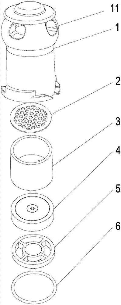
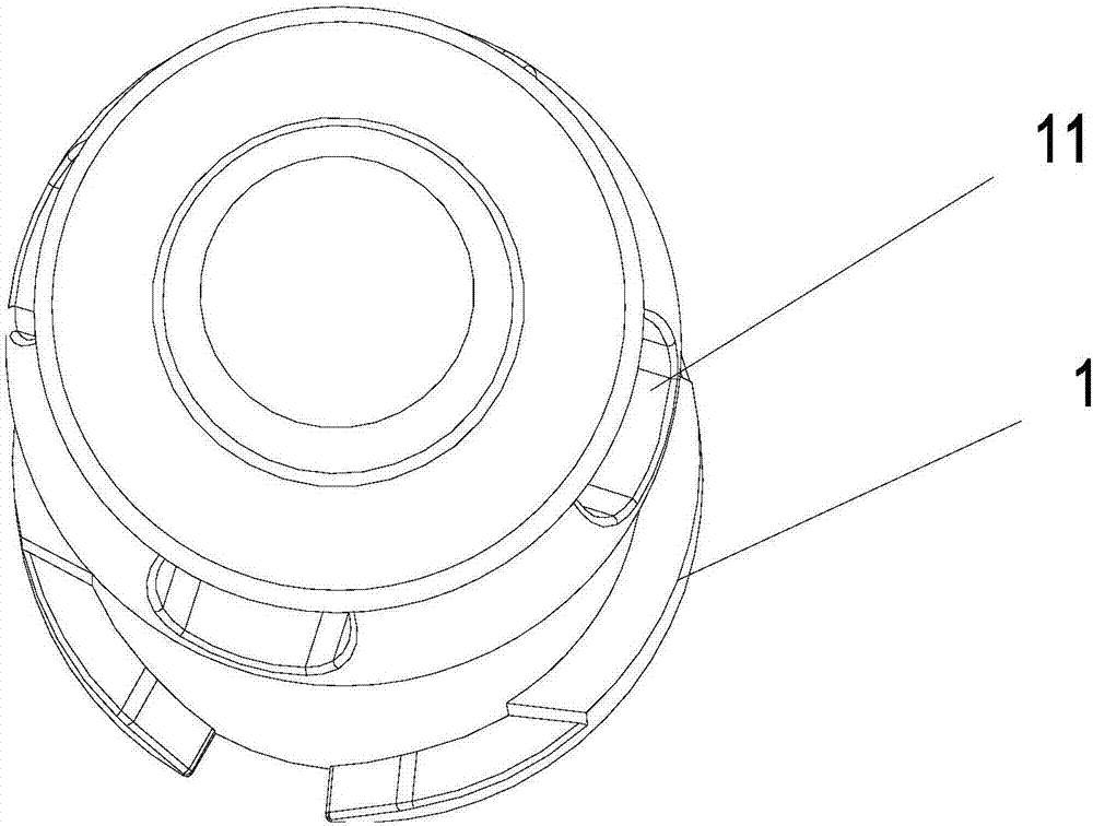
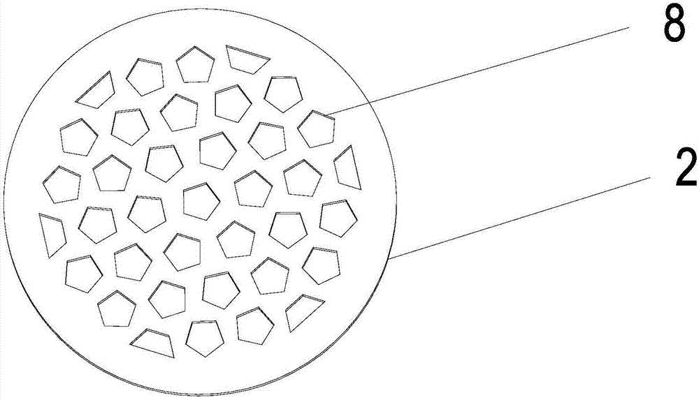
[0027] like Figure 1-7 As shown, the multi-stage particle cutter includes an air intake hood 1, the top of the air intake hood 1 is provided with an air intake hole 11, and the air intake hood 1 is sequentially provided with a filter screen 2, a nozzle 3, and a filter screen connected to each other from top to bottom. A cutting box 4, a second cutting box 5 and a sealing ring 6, the second cutting box 5 is sealed and connected with the inner wall of the air intake cover 1, the filter screen 2 is provided with several first filter holes 8, the nozzle 3 and the filter screen 2 There is an impact chamber 12 formed between them, the nozzle 3 is located at the bottom of the impact chamber 12 to be provided with a second filter hole 9, the upper surface of the first cutting box 4 is provided with a first adsorption layer 10 corresponding to the second filter hole 9 up and down, the first On the opposite side of the first adsorption layer 10, the cutting box 4 is provided with a pri...

Embodiment 2

[0030] PM2.5: The difference from Example 1 is that when the particles enter the nozzle, a certain weight will be generated due to the inertia of the air flow. When the diameter of the particles is ≥0.4 mm, they will stay in the nozzle and will not enter the cutter. In the next part, particles with a diameter of 4 microns, When it hits the first cutting box 4, it will be absorbed by the silicone oil on the surface of the first cutting box 4, and particles with a diameter of ≤4 microns enter the second cutting box 5 through the hexagonal hole in the middle of the first cutting box 4. Inertia will produce a certain weight. When the particle diameter > 2.5 microns, it hits the second cutting box 5 and will be absorbed by the silicone oil on the surface of the second cutting box 5. Particles with a diameter of ≤ 2.5 microns pass through the middle of the second cutting box 5 Four fan-shaped holes enter the inside of the instrument for detection.

Embodiment 3

[0032]PM10: The difference from Example 1 is that when the particles enter the nozzle from the surroundings, a certain weight will be generated due to the inertia of the airflow. When the diameter of the particles is ≥ 1 mm, they will stay in the nozzle and will not enter the lower part of the cutter. Particles with a diameter of less than 1 mm enter the first cutting box 4 through the four hexagonal second filter holes 9 in the middle of the nozzle 3, and a certain weight will be generated due to the inertia of the air flow. When the diameter of the particles is greater than 12 microns, When it hits the first cutting box 4, it will be absorbed by the silicone oil on the surface of the first cutting box 4, and particles with a diameter of ≤12 microns enter the second cutting box 5 through the hexagonal hole in the middle of the first cutting box 4, due to the airflow Inertia will produce a certain weight. When the diameter of the particle is larger than 10 microns, it hits the ...


PUM


Abstract

The invention mainly discloses a multilevel particle cutter. The cutter comprises an air intake hood, as well as a filtering screen, a nozzle, cutting boxes and a sealing ring which are in the air intake hood; the cutting boxes and an inner wall of the air intake hood are connected in tight connection; the filtering screen and the nozzle are provided with filtering apertures; an upper surface of a first cutting box is provided with a first adsorption layer which is up and down corresponding to filtering apertures on the top, primary filtering apertures are arranged on one side of the first cutting box opposite to the first adsorption layer; the upper surface of a second cutting box is provided with a second adsorption layer which is up and down corresponding to primary filtering apertures, and secondary filtering apertures are arranged on one side of the second cutting box opposite to the second adsorption layer. The structure has good cutting effects, the adsorption layer and the filtering apertures on the upper cutting box are respectively corresponding to the filtering apertures and the adsorption layer on the lower cutting box, in order to avoid adsorption of large particles in the filtering apertures which causes obstruction of filtering apertures in the effect of inertia; the adsorption layers absorb large particles, in order to facilitate cleaning of particles, and at the same time avoid impact of large particles and other particles after adsorption which causes reduction of cutting efficiency.

Description

technical field [0001] The invention relates to a particle filtering device, in particular to a multi-stage particle cutter. Background technique [0002] With the rapid development of social economy and the rapid increase in the number of motor vehicles, my country's ambient air pollution is becoming more and more significant, regional air pollution problems are becoming more and more serious, and air PM2.5 pollution in developed areas is becoming more and more serious, which has become the trend of future pollution development. , not only reduces the visibility, but also leads to an increase in the morbidity and mortality of the circulatory system and respiratory system of residents, which is harmful to human health. [0003] At present, the previous particle cutters are not only complex in structure, high in process requirements, expensive, inconvenient to operate and transport, easy to maintain and difficult to promote, but also the filter device on the cutter is usually ...

Claims


Application Information

Patent Timeline
Patent Type & Authority Applications(China)
IPC IPC(8): G01N1/28G01N1/22
CPCG01N1/22G01N1/2205G01N1/2273G01N1/28
Inventor 徐永根段小丽徐劲松
Owner HANGZHOU KEMAI ENVIRONMENTAL SCI & TECH CO LTD
Why Eureka
Try Eureka