
Drum-type granulating machine for biological organic fertilizers

A bio-organic fertilizer and granulator technology, applied in the direction of granulation in the rotary tank, can solve the problems of reducing production efficiency, low production efficiency, affecting granulation quality and pelleting rate, etc., and achieves reasonable structure and high production efficiency Effect

Active Publication Date: 2017-08-15
SHANDONG HUAYI HEAVY IND CO LTD
View PDF10 Cites 0 Cited by
  • Summary
  • Abstract
  • Description
  • Claims
  • Application Information

AI Technical Summary

Problems solved by technology

Due to the inevitable generation of ungranulated powder during the granulation process, this not only increases the load of the screening process, but also increases the transportation and turnover of a lot of materials, resulting in high energy consumption and low production efficiency.
In addition, in actual use, due to the high humidity of bio-organic fertilizer granulation raw materials, it is easy to stick to the inner wall of the drum. If these wall materials are not cleaned in time, they will accumulate more and more, which will seriously affect the granulation quality and pelleting rate.
If it is necessary to stop the machine when cleaning the wall material, frequent parking will affect the requirements of continuous and stable production and reduce production efficiency

Method used


Image

  • Drum-type granulating machine for biological organic fertilizers
  • Drum-type granulating machine for biological organic fertilizers
  • Drum-type granulating machine for biological organic fertilizers

Examples


Embodiment Construction

[0015] The present invention will be further described below in conjunction with the accompanying drawings and specific embodiments.

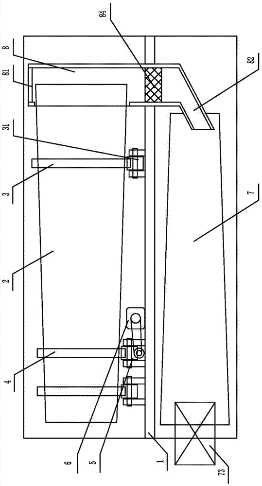
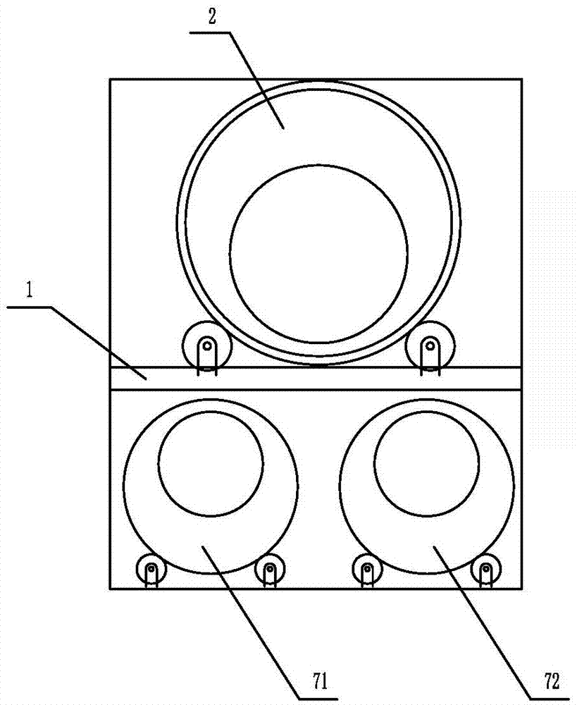
[0016] Such as figure 1 , figure 2 As shown, the drum-type bio-organic fertilizer granulator of the present invention includes a bracket 1, an upper drum 2 driving motor rotatably installed on the upper end of the bracket 1, and the outer wall of the upper drum 2 is fixedly equipped with a track ring 3 and Gear ring 4, the gear ring 4 is connected with the drive motor 6 through the drive gear 5, and the track ring 3 is rollingly mounted on the idler roller 31, as Figure 5 As shown, the idler roller 31 is provided with a ring groove with a U-shaped cross section, and the track ring 3 is clamped in the ring groove of the idler roller 31 .

[0017] The inner cavity of the upper drum 2 is a conical structure with a small diameter at the front end and a large diameter at the rear end. During installation, as long as the lowest point of the rear ...


PUM


Abstract

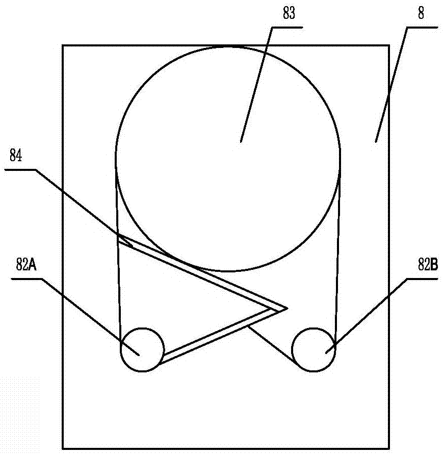
The invention relates to chemical fertilizer production equipment, in particular to a drum-type granulating machine for biological organic fertilizers. The machine comprises a support, an upper drum which can be rotatably mounted at the upper end of the support and a driving motor, wherein an orbital ring and a geared ring are fixedly mounted on the outer wall of the upper drum; the geared ring is in transmission connection with the driving motor by a driving gear; the orbital ring is mounted on a carrier roller in a rolling manner; an inner chamber of the upper drum is of a conical structure of which the diameter of the front end is small and the diameter of the rear end is large; a transfer hopper is arranged at the rear end of the upper drum; a ventilation hole is formed in the upper end of the transfer hopper; a discharging pipe is arranged at the lower end of the transfer hopper; the side wall of the transfer hopper is in butt joint with the upper drum; a lower drum can be rotatably mounted under the support; an inner chamber of the lower drum is of a conical structure of which the diameter of the front end is large and the diameter of the rear end is small; and the rear end of the lower drum is in butt joint with the discharging pipe. The reciprocating drum-type granulating machine for the biological organic fertilizers has reasonable structure, is high in production efficiency, can complete processes such as membrane coating, sieving and drying can be completed once, and meanwhile, wall attachment materials can be removed without needing shutdown of the machine.

Description

technical field [0001] The invention relates to a chemical fertilizer production equipment, in particular to a drum-type bio-organic fertilizer granulator. Background technique [0002] In the production process of bio-organic fertilizer, the drum granulator is commonly used to granulate the raw materials of bio-organic fertilizer. The outer wall of the traditional drum granulator is provided with multiple circular tracks, at least one of which is a rack, and the drum is driven by gear meshing. Rotate, and at least two other rails rest on grooved support wheels to keep the drum in balance. In order to make the fertilizer particles roll from the front end to the rear end, the drum should be set at an inclination, and the gravity of the material can be used to make it move backwards, which will increase the lateral force of the drum and require higher requirements for the moving parts of the supporting drum. The material inlet and outlet of this drum granulator are respective...

Claims


Application Information

Patent Timeline
Patent Type & Authority Applications(China)
IPC IPC(8): B01J2/12
CPCB01J2/12
Inventor 周洪亮韩正青楚宪省董新刚
Owner SHANDONG HUAYI HEAVY IND CO LTD
Learn More