Low-cost radio frequency differential amplifier

A differential amplifier, a low-cost technology, applied in the direction of differential amplifiers, radio frequency amplifiers, amplifiers, etc., can solve the problems of few curved lines, waste of surrounding area, unsuitable for other circuits, etc., to reduce chip area, reduce cost, The effect of compact layout layout

Active Publication Date: 2017-08-15
SHANGHAI HUAHONG GRACE SEMICON MFG CORP
View PDF7 Cites 4 Cited by
  • Summary
  • Abstract
  • Description
  • Claims
  • Application Information

AI Technical Summary

Problems solved by technology

[0004] Due to the working principle of the input balun and the output balun and the limitation of the circuit structure, the width and height of the input balun and the output balun are generally approximately square, and the inductance values ​​of the input and output baluns are different (the input and output impedances of NMOS tubes are different. The same), the input balun and output balun are usually a group of mutually coupled symmetrical metal lines with a planar structure, and are connected to another layer with a via at the intersection and then returned to the starting plane through the via (the dotted line in the figure That is, the via holes and the metal lines arranged on other layers), the width of the metal lines and the spacing between the metal lines are determined by the circuit characteristics. Usually, the input and output of the RF circuit are connected in a straight line, and the wiring is rarely bent to avoid unnecessary RF coupling, so the traces are usually as figure 2 In the form shown, the input RF signal RFin passes through the input balun, the RF amplifying unit, and the output balun in sequence, and the three are arranged along the same axis. Although the RF tube is much larger than the tube of a general logic circuit, it is relatively larger than the input balun and the output balun. The len is still much smaller, so that the layout looks like a structure with two big ends (input balun, output balun) and a small middle (RF amplifier unit). Considering the circuit performance, it is not suitable to place other circuits around the radio frequency circuit, resulting in Serious waste of area

Method used


Image

  • Low-cost radio frequency differential amplifier
  • Low-cost radio frequency differential amplifier
  • Low-cost radio frequency differential amplifier

Examples


Embodiment Construction

[0026] The implementation of the present invention is described below through specific examples and in conjunction with the accompanying drawings, and those skilled in the art can easily understand other advantages and effects of the present invention from the content disclosed in this specification. The present invention can also be implemented or applied through other different specific examples, and various modifications and changes can be made to the details in this specification based on different viewpoints and applications without departing from the spirit of the present invention.

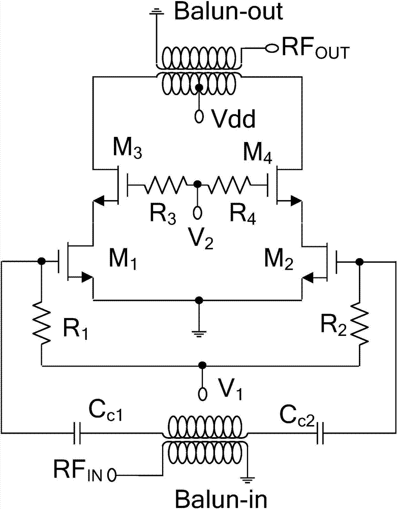
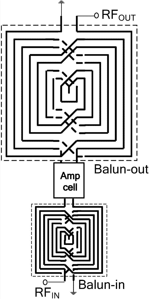
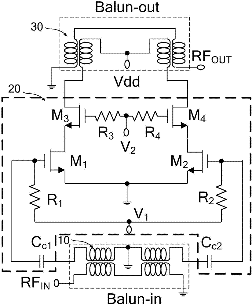
[0027] image 3 It is a circuit structure diagram of a low-cost radio frequency differential amplifier of the present invention. Such as image 3 As shown, a low-cost RF differential amplifier of the present invention includes an input balun (input unbalanced-balanced converter, Balun-in) 10, a differential radio frequency circuit (Amp cell) 20, and an output balun (output balanced-unbalan...


PUM


Abstract

The invention discloses a low-cost radio frequency differential amplifier. The differential amplifier comprises an input balun, a differential radio frequency circuit, and an output balun, wherein the input balun is used for outputting an input radio frequency single-ended signal by converting the same into a balancing mode from an unbalancing mode by use of two sub-baluns so as to obtain a differential signal required by the differential radio frequency circuit; the differential radio frequency is used for amplifying the balanced radio frequency signal output by the input balun; and the output balun is used for outputting the balanced radio frequency signal, which is output by the different radio frequency circuit, by converting the same into the unbalancing through two sub-baluns. By use of the differential amplifier disclosed by the invention, the layout of the system is compact while the radio frequency performance of the circuit is guaranteed, the chip area around an active device is sufficiently utilized, and the cost is effectively lowered.

Description

technical field [0001] The invention relates to the field of radio frequency circuit design, in particular to a low-cost radio frequency differential amplifier. Background technique [0002] With the development of IoT (Internet Of Things, Internet of Things) wireless communication technology, compact circuit and layout design has become a key technology to reduce the cost of RFIC chips. The input and output of the differential RF amplifier are usually matched by a balun, and the balun occupies a major chip area. [0003] figure 1 It is a circuit structure diagram of a traditional RF differential amplifier. Such as figure 1 As shown, the traditional RF differential amplifier consists of an input balun (Balun-in), a differential RF circuit and an output balun (Balun-out). The input balun (Balun-in) completes the input single-ended signal RFIN from unbalanced to balanced The conversion to obtain the differential signal required by the differential radio frequency circuit, ...

Claims


Application Information

Patent Timeline
Patent Type & Authority Applications(China)
IPC IPC(8): H03F3/193H03F3/45
CPCH03F3/193H03F3/45381H03F2200/451
Inventor 戴若凡
Owner SHANGHAI HUAHONG GRACE SEMICON MFG CORP
Why Eureka
Try Eureka