
Quantitative weighing device and coffee making machine

A weighing and quantity technology, applied in beverage preparation devices, home appliances, applications, etc., can solve the problems of high quality, low cost and high machine cost that cannot satisfy consumers, and achieve high cost performance, simple structure, The effect of easy operation

Active Publication Date: 2017-08-18
FORTUNE TECH MFG CO LTD
View PDF6 Cites 0 Cited by
  • Summary
  • Abstract
  • Description
  • Claims
  • Application Information

AI Technical Summary

Problems solved by technology

[0002] With the improvement of people's material living standards, people's life taste is also gradually improved. In order to meet consumers' needs for high quality, precise control and convenient life, many similar weighing machines have been launched on the market, but most of them are Using complex structures such as gravity sensors and liquid crystal displays, this type of machine has high precision in weight control, but the cost of the machine is high, which cannot satisfy consumers' pursuit of low-cost, cost-effective products; some machines use the specified grinding time to control the powder. Weight, the accuracy of this type of machine to control the weight of powder is insufficient, which cannot satisfy consumers' pursuit of high-quality products, convenient operation, and precise weight control

Method used


Image

  • Quantitative weighing device and coffee making machine
  • Quantitative weighing device and coffee making machine
  • Quantitative weighing device and coffee making machine

Examples


Embodiment Construction

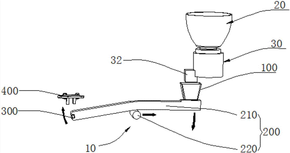
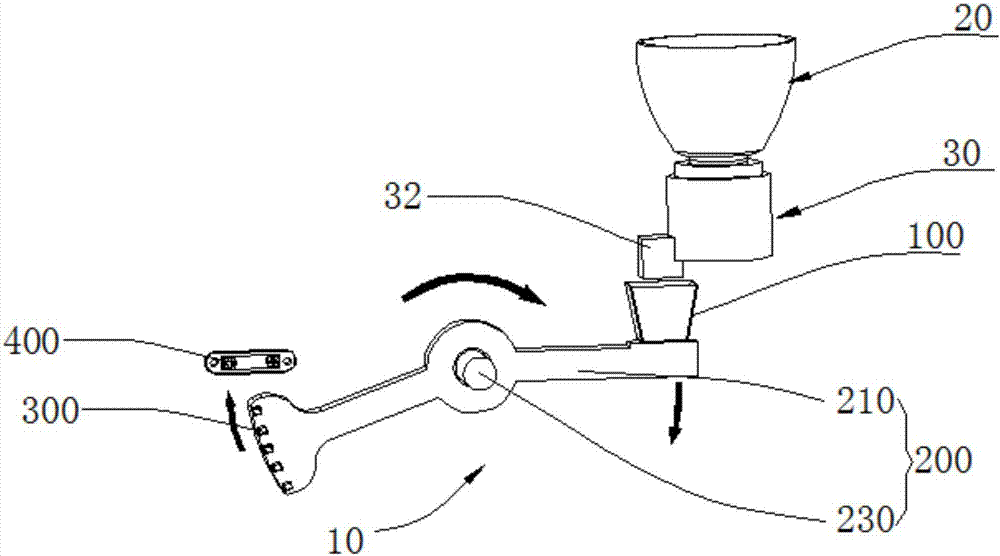
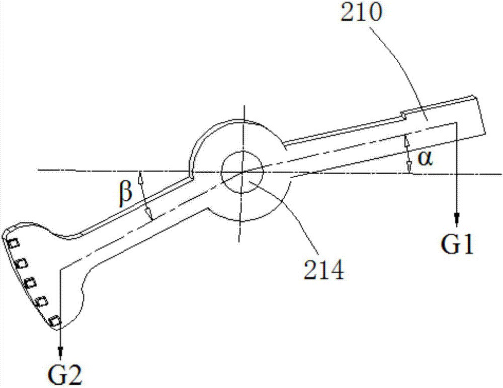
[0031] Please also refer to Figure 1 to Figure 2 , the present invention provides a quantitative weighing device 10 , including a loader 100 , a swing assembly 200 , a stopper 300 and a photoelectric switch 400 . The swing assembly 200 includes a swing rod 210, the swing rod 210 has a swing fulcrum, the loader 100 and the stopper 300 are both arranged on the swing rod 210, and are respectively located on the swing Both sides of the fulcrum. The photoelectric switch 400 and the stopper 300 are arranged on the same side of the swing fulcrum. When feeding, with the addition of materials in the loader 100, the swing rod 210 starts to swing and drives the movement of the stopper 300, and the photoelectric switch is located on the movement path of the stopper 300, when the When the block 300 moves between the emitter and the receiver of the photoelectric switch 400, the photoelectric switch 400 is turned off to form a photoelectric induction signal output, thereby converting the ...


PUM


Abstract

The invention discloses a quantitative weighing device, which comprises a charger, a swinging assembly, a stopping block and a photoelectric switch, wherein the swinging assembly comprises a swinging rod; a swinging pivot is formed in the swinging rod; both the charger and the stopping block are arranged on the swinging rod and the charger and the stopping block are arranged at two sides of the swinging pivot; the photoelectric switch and the stopping block assembly are arranged at the same side of the swinging pivot; the swinging rod can swing and can drive the stopping block to move along with addition of materials to the charger; the photoelectric switch is located on a movement path of the stopping block; and the photoelectric switch is disconnected when the stopping block moves to a space between a transmitting electrode and a receiving electrode of the photoelectric switch, so that photoelectric induction signal output is achieved. The invention further provides a coffee making machine comprising the quantitative weighing device. The quantitative weighing device provided by the invention is simple in structure, convenient to operate and high in cost performance, and precise configuration of the materials can be achieved.

Description

technical field [0001] The invention relates to the technical field of weighing devices, in particular to a quantitative weighing device and a coffee machine. Background technique [0002] With the improvement of people's material living standards, people's life taste is also gradually improved. In order to meet consumers' needs for high quality, precise control and convenient life, many similar weighing machines have been launched on the market, but most of them are Using complex structures such as gravity sensors and liquid crystal displays, this type of machine has high precision in weight control, but the cost of the machine is high, which cannot satisfy consumers' pursuit of low-cost, cost-effective products; some machines use the specified grinding time to control the powder. Weight, the accuracy of this type of machine to control the weight of powder is insufficient, which cannot satisfy consumers' pursuit of high-quality products, convenient operation, and precise we...

Claims


Application Information

Patent Timeline
Patent Type & Authority Applications(China)
IPC IPC(8): A47J31/40A47J31/42
CPCA47J31/40A47J31/42
Inventor 王冬雷熊艳
Owner FORTUNE TECH MFG CO LTD
Learn More