PCB milling cutter with replaceable cutter head

A technology of cutter heads and milling cutters, which is applied in the direction of milling cutters, milling machine equipment, manufacturing tools, etc., can solve the problems affecting the overall rigidity of milling cutters, high scrap rate, and general performance, so as to save the part of the cutter bar, improve stability, The effect of a stable connection

Inactive Publication Date: 2017-08-18
江苏芯力特电子科技有限公司
View PDF6 Cites 0 Cited by
  • Summary
  • Abstract
  • Description
  • Claims
  • Application Information

AI Technical Summary

Problems solved by technology

At present, the production process of milling cutter is mainly to process the whole alloy raw material. After the milling cutter is worn or broken, the whole cutter can only be scrapped or the worn cutter head can be ground into a small size. This method also has a high scrap rate, and the processed The performance is average, and there is also the method of rod-type welding production. Other cheaper metals are used to make the milling cutter holder, and the cutter head and the cutter holder are welded together. This processing method requires high precision, and due to different materials , affecting the use, there is also the method of continuing to use the remaining part after cutting off the worn part, which may cause the cutting edge part to be too long and affect the overall rigidity of the milling cutter

Method used


Image

  • PCB milling cutter with replaceable cutter head
  • PCB milling cutter with replaceable cutter head
  • PCB milling cutter with replaceable cutter head

Examples


Embodiment 1

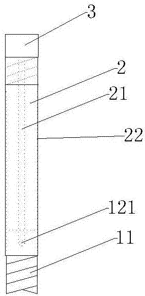
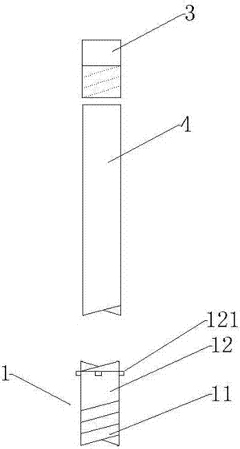
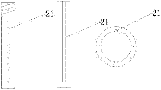
[0017] Such as figure 1 , figure 2 , image 3 As shown, a PCB milling cutter with a replaceable cutter head includes a cutter head 1, a sleeve 2, a fixed end 3 for closing the top opening of the sleeve 2, and a fixing rod for fixing the cutter head 1 4. Both ends of the casing 2 are open, one end is connected to the cutter head 1, and the other end is connected to the fixed end 3, and an external thread is provided on the top of the casing 2, and the fixed end 3 is provided with There are internal threads, the sleeve 2 and the fixed end 3 are threadedly connected, and the inner wall of the sleeve 2 is evenly distributed along the length direction of the sleeve 2. Four long grooves 21 can also be used to set One turn of the gear turning card slot can make the space between the cutter head 1 and the sleeve 2 more firm and prevent slippage. The end of the long slot 21 close to the fixed end 3 opens to the top of the sleeve 2. One end close to the cutter head 1 is closed, and ...


PUM


Abstract

The invention discloses a PCB milling cutter with a replaceable cutter head. The PCB milling cutter comprises the cutter head, a casing pipe, a fixing end used for closing an opening in the top end of the casing pipe, and a fixing rod used for fixing the cutter head. The two ends of the casing pipe are opened, one end is connected with the cutter head, and the other end of the casing pipe is connected with the fixing end. A plurality of long-strip grooves are evenly distributed in the inner wall of the casing pipe in the length direction of the casing pipe. The ends, close to the fixing end, of the long-strip grooves are opened to the top end of the casing pipe, and the ends, close to the cutter head, of the long-strip grooves are closed. The cutter head comprises a connecting part and a blade part. A plurality of protrusions are arranged on the side edge of the connecting part and correspond to the long-strip grooves in position, number and size. The fixing rod is a cylinder, the diameter of the fixing rod is consistent with the inner diameter of the casing pipe, and the fixing rod is located in the casing pipe and between the cutter head and the fixing end. The PCB milling cutter has the beneficial effects that cutter head replacement can be achieved, cutter rod waste is avoided, the structure is simple, and installation is firm.

Description

technical field [0001] The invention relates to a PCB milling cutter with a replaceable cutter head, which belongs to the technical field of milling cutters. Background technique [0002] The PCB milling cutter is used in the post-process. The main purpose is to use this cutter to cut the finished circuit board into the final product size required by the individual customers. It is a rotary cutter with one or more cutter teeth. At present, the production process of milling cutter is mainly to process the whole alloy raw material. After the milling cutter is worn or broken, the whole cutter can only be scrapped or the worn cutter head can be ground into a small size. This method also has a high scrap rate, and the processed The performance is average, and there is also the method of rod-type welding production. Other cheaper metals are used to make the milling cutter holder, and the cutter head and the cutter holder are welded together. This processing method requires high pr...

Claims


Application Information

Patent Timeline
Patent Type & Authority Applications(China)
IPC IPC(8): B23C5/16
CPCB23C5/16
Inventor 张文杰谢亮金湘亮
Owner 江苏芯力特电子科技有限公司
Why Eureka
Try Eureka