
Spindle broach device and turret type numerical control milling machine

A tool device and spindle technology, applied in the field of machine tools, can solve the problems of tool machine tool coordinate Z value deviation, affect efficiency, easily damaged thread ejector, etc., and achieve the effect of tool change accuracy and speed improvement, tool change convenience, and accuracy improvement.

Inactive Publication Date: 2017-08-18
PURI SETH XIAMEN MACHINERY TECH CO LTD
View PDF6 Cites 0 Cited by
  • Summary
  • Abstract
  • Description
  • Claims
  • Application Information

AI Technical Summary

Problems solved by technology

[0004] Because the locking tool is completed by screwing the thread, due to the strength of the individual and the external air pressure of the pneumatic tool locking device, it is easy to cause the tension of the locking tool to be different each time, resulting in each tool and the spindle. The contact stress of the tool is different, so the Z value of the machine tool coordinates also deviates
At the same time, the thread is also easily damaged for a long time, resulting in the instability of the precision of the machine tool processing products
In layman's terms, the main shaft lock tool means that the tool handle and the ejector rod are locked by the thread, and the tool handle is tightened by the ejector rod, so that the tool handle and the taper of the inner hole of the main shaft fit together to achieve the structure of locking the tool; since the machine tool adopts Manually lock the tool spindle, the processing of products requires multiple tools, and the traditional method is manual or irregular force locking, resulting in different effects, resulting in errors in the tool locking position; resulting in the need for tool calibration every time a tool is changed, affecting efficiency , and the operating intensity of the personnel
Pneumatic locking mechanism, due to the difference in air pressure and operation, will also produce the above phenomenon. If it is used for a long time, it is also easy to damage the threaded ejector rod.
Most of the processed products require several tools, resulting in unstable coordinates of the machine tool where the tool is located after each tool change
To achieve precision, the tool must be set every time, which affects the processing efficiency and increases the intensity of manual operation
Machine tools with automatic tool change are expensive

Method used


Image

  • Spindle broach device and turret type numerical control milling machine
  • Spindle broach device and turret type numerical control milling machine
  • Spindle broach device and turret type numerical control milling machine

Examples


Embodiment

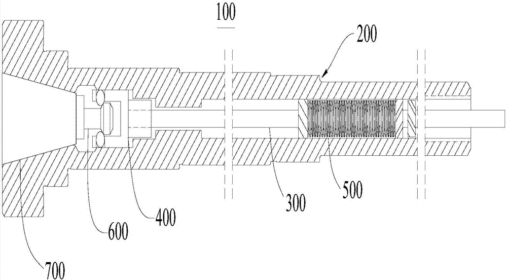
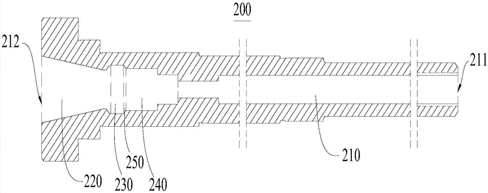
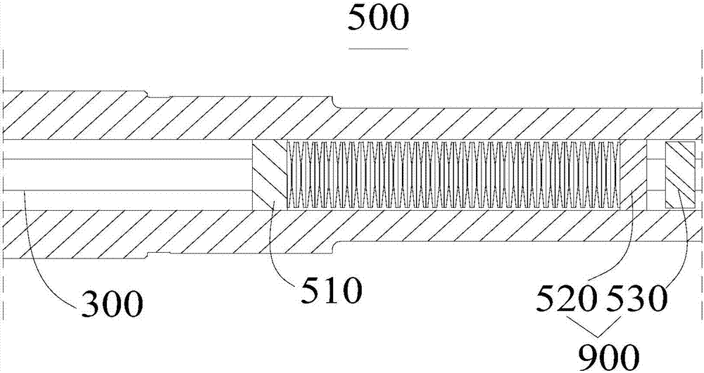
[0033] A turret type CNC milling machine (not shown), on which a milling machine base, a milling machine bed, a workbench, a milling machine column, a milling head and a main shaft broaching device 100 ( figure 1 shown), the milling machine bed is set on the milling machine base, the workbench is set on the milling machine bed, the lower end of the column is connected to the milling machine bed, the upper end of the column is connected to the milling head, and the spindle broaching device 100 is set on the milling head, wherein the milling machine Base, milling machine bed, workbench, milling machine column, milling head are not the core of the present invention, those skilled in the art can realize by referring to the prior art, do not repeat them here.

[0034] Please refer to figure 1 , the present embodiment provides a spindle broaching device 100 , which includes a spindle 200 , a push rod 300 , a claw 400 , and an elastic member 500 .

[0035] to combine figure 1 and ...


PUM


Abstract

The invention provides a spindle broach device and a turret type numerical control milling machine and relates to the field of machine tools. The spindle broach device comprises a spindle, an ejector rod, an elastic piece and a pulling claw. A containing cavity is formed in the spindle and provided with a first end and a second end opposite to the first end. The ejector rod is slidably arranged in the containing cavity in the direction from the second end to the first end. The pulling claw is connected to the end, close to the first end, of the ejector rod. The end, close to the second end, of the ejector rod is connected with a power device so that the ejector rod can be driven to slide from the second end to the first end. The elastic piece is arranged in the containing cavity. A broach comprises a broach handle and a pulling nail. The pulling claw clings to the pulling nail when the ejector rod slides from the first end to the second end and releases the pulling nail when the ejector rod slides from the second end to the first end. The structure is simple, fast broach locking is achieved through cooperation of the pulling claw, the ejector rod and the elastic piece, and broach locking is quite convenient. The turret type numerical control milling machine comprises the spindle broach device and can improve the precision when a machine tool machines a finished product through a plurality of tools.

Description

technical field [0001] The invention relates to the field of machine tools, in particular to a spindle broaching device and a turret-type numerical control milling machine. Background technique [0002] With the development of the economy and the progress of society, it has become an inevitable industry consensus to improve efficacy and optimize processing time. All kinds of machine tool equipment are more and more developed in the direction of safety, high efficiency, energy saving, convenient use, space saving, and multi-functionality of one machine. As an important member of the processing industry, CNC milling machines are no exception. [0003] At present, the spindle locking tool of the turret type CNC milling machine is completed by mechanically screwing the threaded ejector rod at one end through the central hole of the spindle and the threaded opening on the blade. 1: Manually use a wrench to complete the tightening work; 2: Use an external pneumatic rotary lockin...

Claims


Application Information

Patent Timeline
Patent Type & Authority Applications(China)
IPC IPC(8): B23C5/26
CPCB23C5/26
Inventor 张书豪黄志萍
Owner PURI SETH XIAMEN MACHINERY TECH CO LTD
Learn More