
Ultra-high-speed motorized spindle automatic tool changer

A technology of automatic tool change and electric spindle, which is applied in the direction of positioning device, clamping, and support to achieve the effect of stable operation, guaranteeing clamping force, and reducing overlapping links.

Active Publication Date: 2016-09-21
江西衡源智能装备股份有限公司
View PDF7 Cites 0 Cited by
  • Summary
  • Abstract
  • Description
  • Claims
  • Application Information

AI Technical Summary

Problems solved by technology

[0003] The purpose of the present invention is to provide an ultra-high-speed electric spindle automatic tool changer, which effectively solves the problems of tool application diversity, electric spindle operation stability and tool change accuracy

Method used


Image

  • Ultra-high-speed motorized spindle automatic tool changer
  • Ultra-high-speed motorized spindle automatic tool changer
  • Ultra-high-speed motorized spindle automatic tool changer

Examples


Embodiment Construction

[0033] The present invention will be described in further detail below in conjunction with the accompanying drawings.

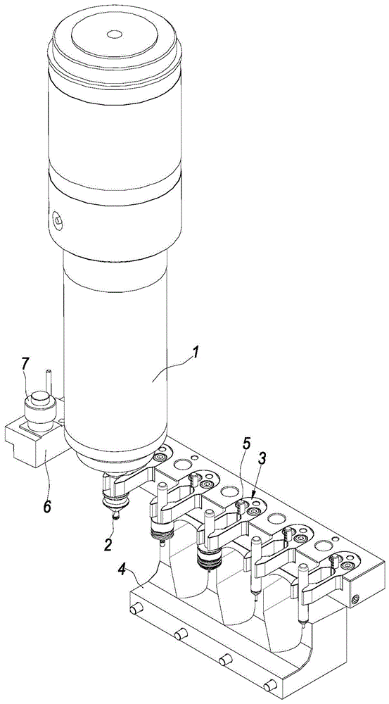
[0034] figure 1 It schematically shows an automatic tool changer for an ultra-high-speed electric spindle according to an embodiment of the present invention.

[0035] Such as figure 1 As shown, the ultra-high-speed electric spindle automatic tool change device includes an electric spindle 1, a caliper 3, a caliper mounting seat 4, an air blowing rod 5, a tool change checker 6 and a tool length measuring device 7, and the tool change checker 6 is set on the caliper One side of the mounting base 4, the tool length measuring device 7 is installed on the tool changing checker 6, there are five cutters 2, and five calipers 3.

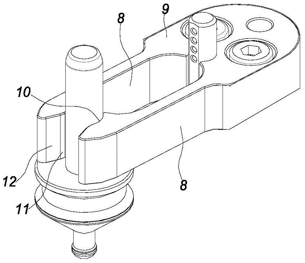
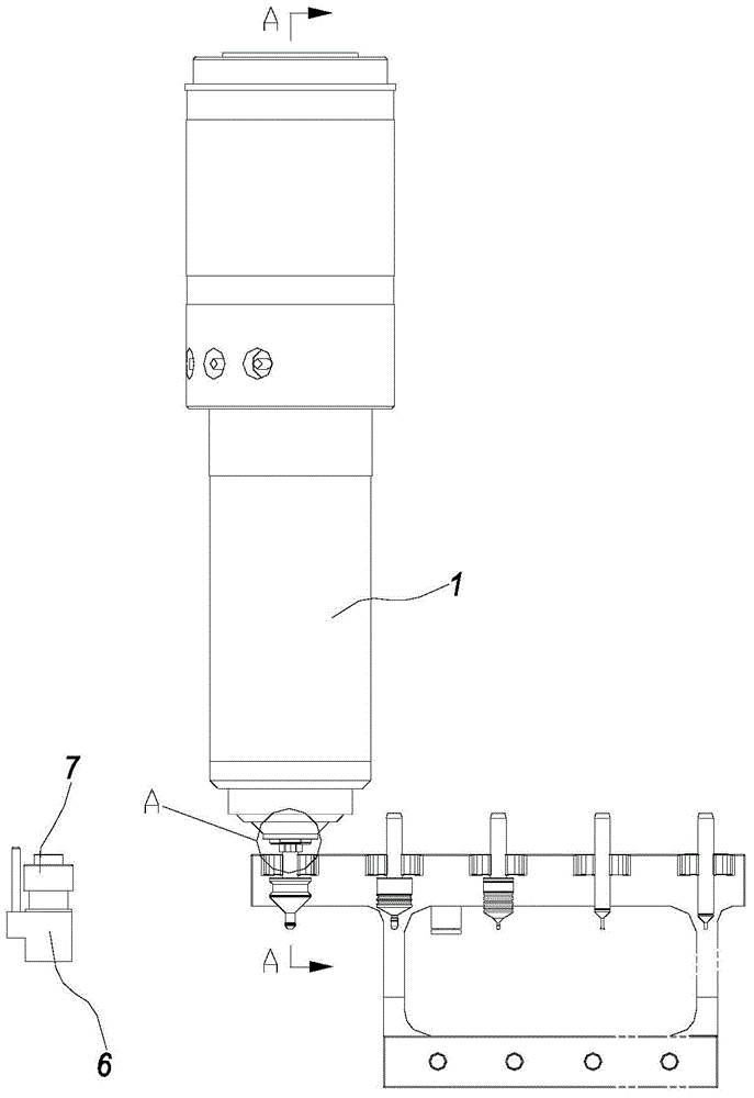
[0036] Such as figure 1 , 2 , 3, the caliper 3 is composed of two elastic jaws 8 and a positioning seat 9, the positioning seat 9 is fixed to the caliper mounting seat 4 by bolts, and the two elastic jaws 8 are symmetrically connected ...


PUM


Abstract

The invention discloses a superspeed motorized spindle automatic tool changer. The superspeed motorized spindle automatic tool changer comprises a motorized spindle, calipers and a calipers installation base. The calipers can clamp a tool tightly and are installed in the calipers installation base. The motorized spindle is used for being detachably connected with the tool and moving the tool in or out of the calipers from the lateral portion of the calipers. The invention further discloses a superspeed motorized spindle automatic tool changing method. The superspeed motorized spindle automatic tool changing method comprises the steps that the motorized spindle is moved to the front end of the calipers, and the tool is pushed into the calipers to be clamped tightly; the motorized spindle is separated from the tool and is moved to a tool changing detector to carry out tool changing logic checking; after tool changing is detected to be successful, the motorized spindle is moved to the upper end of next calipers, the tool is installed in a chuck of a spring clamping tool, and the chuck of the spring clamping tool on the motorized spindle clamps the tool; the motorized spindle and the clamped tool are transversely moved out of the calipers, the length of the tool is measured, and tool changing is finished. The tool is clamped reliably and positioned accurately, the tool changing precision of the motorized spindle is high, tool changing is accurate and efficient, and stability of motorized spindle running is guaranteed.

Description

technical field [0001] The invention relates to the field of numerical control machining center machine tools, in particular to an automatic tool changing device for an ultra-high-speed electric spindle of a small machining center. Background technique [0002] Most of the light metal structural parts of consumer electronic products such as mobile phones are quickly cut and formed by small machining centers. The tools of the ultra-high-speed electric spindle tool change system generally use spacer sleeves as bushes, and the diameter of the blade cannot be larger than the spacer sleeve, which limits the application of the tool At the same time, when the tool and the spacer sleeve rotate at high speed together, the spacer sleeve is easy to fly out of the tool, which causes the imbalance of the electric spindle. In addition, the tool with the spacer sleeve is installed on the tool holder, and the cumulative error of the entire assembly will increase. , It is easy to cause inacc...

Claims


Application Information

Patent Timeline
Patent Type & Authority Patents(China)
IPC IPC(8): B23Q3/155
CPCB23Q3/15526B23Q3/15706
Inventor 肖衍盛
Owner 江西衡源智能装备股份有限公司
Learn More