Vehicle air conditioning unit

A technology for air-conditioning units and vehicles, applied to vehicle components, air handling equipment, heating/cooling equipment, etc., can solve the unavoidable rise of cold wind ventilation resistance and achieve the effect of suppressing the rise of ventilation resistance

Inactive Publication Date: 2017-08-18
VALEO JAPAN CO LTD
View PDF1 Cites 4 Cited by
  • Summary
  • Abstract
  • Description
  • Claims
  • Application Information

AI Technical Summary

Problems solved by technology

[0004] However, the warm air guide passage shown in Patent Document 1 is disposed from below the cold air passage of the air mixing chamber to pass above, so even if it is arranged in a part where the wind speed of the cold wind is low, the increase in the ventilation resistance of the cold wind cannot be avoided in the end.

Method used


Image

  • Vehicle air conditioning unit
  • Vehicle air conditioning unit
  • Vehicle air conditioning unit

Examples


Embodiment 1

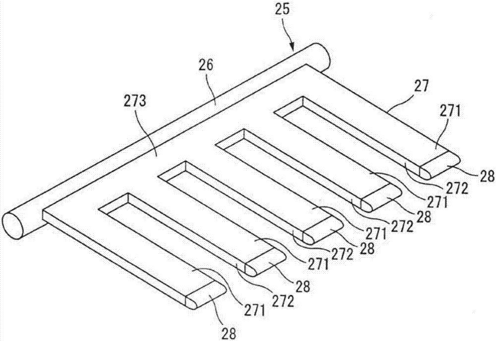
[0054] The damper main body 27 of the movable damper 25 of the first embodiment has at least a plurality of extensions 271 and a plurality of notches 272 between the extensions 271 . Each extension part 271 is a plate-like structure extending linearly, and is connected to the base part 273 extending in the axial direction of the rotation shaft 26 on the side of the rotation shaft 26 in the first embodiment. It should be noted that although the extensions 271 are not shown in the figure, they may be respectively connected to the rotation shafts 26 without passing through the bases 273 .

[0055] In this embodiment, the number of extensions 271, the lateral width of the extensions 271, the interval between adjacent extensions 271, the number of warm air guide passages 20, the inner width of the warm air guide passages 20, and the warm air guide The spacing between the passages 20, 20 corresponds. That is, in this Example 1, as image 3 shown, extension 271 with figure 2 The ...

Embodiment 2

[0072] use Figure 7 The damper body 27 of the movable damper 25 of the second embodiment will be described. Here, the same structures as those of the damper main body 27 of the movable damper 25 of the first embodiment described above are basically denoted by the same reference numerals and their descriptions are omitted.

[0073] The damper main body 27 of the movable damper 25 has extensions 271 corresponding to the number of warm air guide passages 20 (five in this embodiment 2) and a plurality of notches 272 between the extensions 271 . The front end of the extension part 271 has an overlapping part 28, and the above points are the same as those in the first embodiment.

[0074] On the other hand, in the damper body 27 of the movable damper 25 , air guides 274 extending from the base 273 to the overlapping portion 28 along the extended portion 271 are formed on both sides of the extended portion 271 . The extension portion 271 is divided in the left-right direction of t...

Embodiment 3

[0077] use Figure 8 The damper main body 27 of the movable damper 25 of the third embodiment will be described. In addition, about the same structure as the damper main body 27 of the movable damper 25 of Embodiment 1 and 2 demonstrated above, basically the same code|symbol is attached|subjected, and the description is abbreviate|omitted.

[0078] The damper main body 27 of the movable damper 25 has extensions 271 corresponding to the number of warm air guide passages 20 (five in this embodiment 2), and an overlapping portion 28 is provided at the front end of the extensions 271. The above points Same as Example 1. On the other hand, the damper main body 27 of the movable damper 25 is provided with the bridging part 275 between the extension parts 271 and the extension part 271, and the notch part 272 is eliminated. The overlapping portion 28 is also provided at the front end of the bridging portion 275 . Thus, the damper main body 27 is formed into a single plate shape by...


PUM


Abstract

Provided is an air conditioning unit for a vehicle, which can reliably guide a part of the warm air to the upper side of the air mixing chamber by extending the warm air guide passage in the air mixing mode, and can reliably guide the warm air guide passage without extending the warm air guide passage in the full cooling mode. effectively suppress the increase in ventilation resistance. The vehicle air conditioning unit (1) comprises: an air mixing chamber (11), which is arranged in the housing (4), for mixing the air passing through the heating heat exchanger (7) with the air bypassing the heating heat exchanger; The wind guide passage (20), which is arranged in the air flow path (5), guides a part of the warm air from the bottom of the air mixing chamber to the inside; the movable damper (25), which is arranged in the air flow path, has a rotating shaft ( 26) and the damper main body (27), at the lower limit position of the damper main body, the extension part (271) of the damper main body is used to extend the warm air guide passage to the top of the air mixing chamber; in the air mixing mode, the movable damper is used to make the The warm air guide channel is extended.

Description

technical field [0001] This invention relates to a vehicle air conditioning unit in which a warm air guide passage for guiding upward warm air heated by a heating heat exchanger is arranged in an air mixing chamber. Background technique [0002] In the vehicle air conditioner, when the warm air heated by the heating heat exchanger and the cold air bypassing the heating heat exchanger are mixed in the air mixing chamber, in order to promote the mixing of the warm air and the cold air, it is desirable not to be affected by the cold air. The warm air flowing upward from the bottom of the air mixing chamber is guided to the top of the air mixing chamber in an airflow blocking manner. Regarding this point, Patent Document 1 discloses that a warm air guide passage for part of the warm air heated by the heater core (heat exchanger for heating) flowing in the warm air passage flows is arranged in the air mixing chamber, and the warm air The structure that leads from the bottom of t...

Claims


Application Information

Patent Timeline
Patent Type & Authority Applications(China)
IPC IPC(8): B60H1/00
CPCB60H1/00678B60H2001/00092B60H2001/00721B60H1/00664B60H1/00021
Inventor 长野秀树
Owner VALEO JAPAN CO LTD
Why Eureka
Try Eureka