High pressure jet grouting power head

A technology of high-pressure rotary spraying and power head, which is applied in the direction of drilling with liquid/gas jet, drilling equipment, sheet pile wall, etc. It can solve the problems of increased drill pipe length, high center of gravity of drill pipe, and inconvenient installation, so as to prevent leakage , Lower the height of the center of gravity and shorten the longitudinal length

Active Publication Date: 2017-08-18
张家港保税区永大机械有限公司
View PDF9 Cites 0 Cited by
  • Summary
  • Abstract
  • Description
  • Claims
  • Application Information

AI Technical Summary

Problems solved by technology

Therefore, in the rotary jet drilling machine of the prior art, the distance of slurry spraying is relatively short, and the injection effect is poor, thereby affecting the working efficiency of the rotary jet drilling machine
[0004] At the same time, the traditional jet-jet drilling rig can only rotate in the horizontal direction. In the case of drilling pile holes in solid foundations such as rocks and pouring them to form piles, the traditional jet-jet drilling rig has great limitations.
Because relying solely on the rotary drilling action of the alloy drill bit cannot effectively drill holes in the foundation with rocks or stones and complete the high-pressure rotary spraying process
Therefore, there are certain limitations in the rotary jet drilling machine in the prior art
At the same time, the high-pressure rotary spraying power head in the prior art is prone to leakage of the rotary spraying medium (such as: mud, water and air) at the injection part, so there is a defect that the rotary spraying effect is not good
[0005] In addition, the Chinese invention patent application with the reference publication number CN105350913A discloses a "rotary jet drilling machine and its drilling mechanism", which only realizes the transportation of slurry and water, and more importantly, the slurry and water are vertically input into the drill pipe. input, which leads to an increase in the length of the drill pipe, resulting in a higher center of gravity of the entire drill pipe, so there are defects such as inconvenient installation and unstable structure, and it is impossible to control the flow of the three swirling media of mud, water and air. delivery

Method used


Image

  • High pressure jet grouting power head
  • High pressure jet grouting power head
  • High pressure jet grouting power head

Examples


Embodiment Construction

[0102] The present invention will be described in detail below in conjunction with the implementations shown in the drawings, but it should be noted that these implementations are not limitations of the present invention, and those of ordinary skill in the art based on the functions, methods, or structural changes made by these implementations Equivalent transformations or substitutions all fall within the protection scope of the present invention.

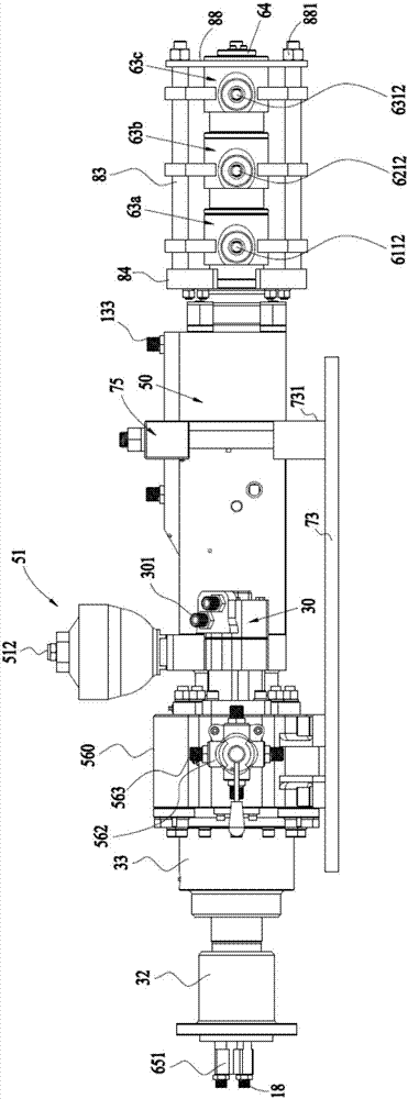
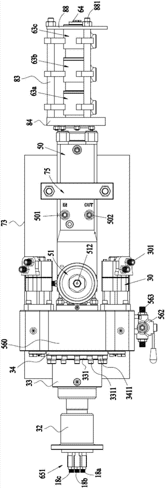
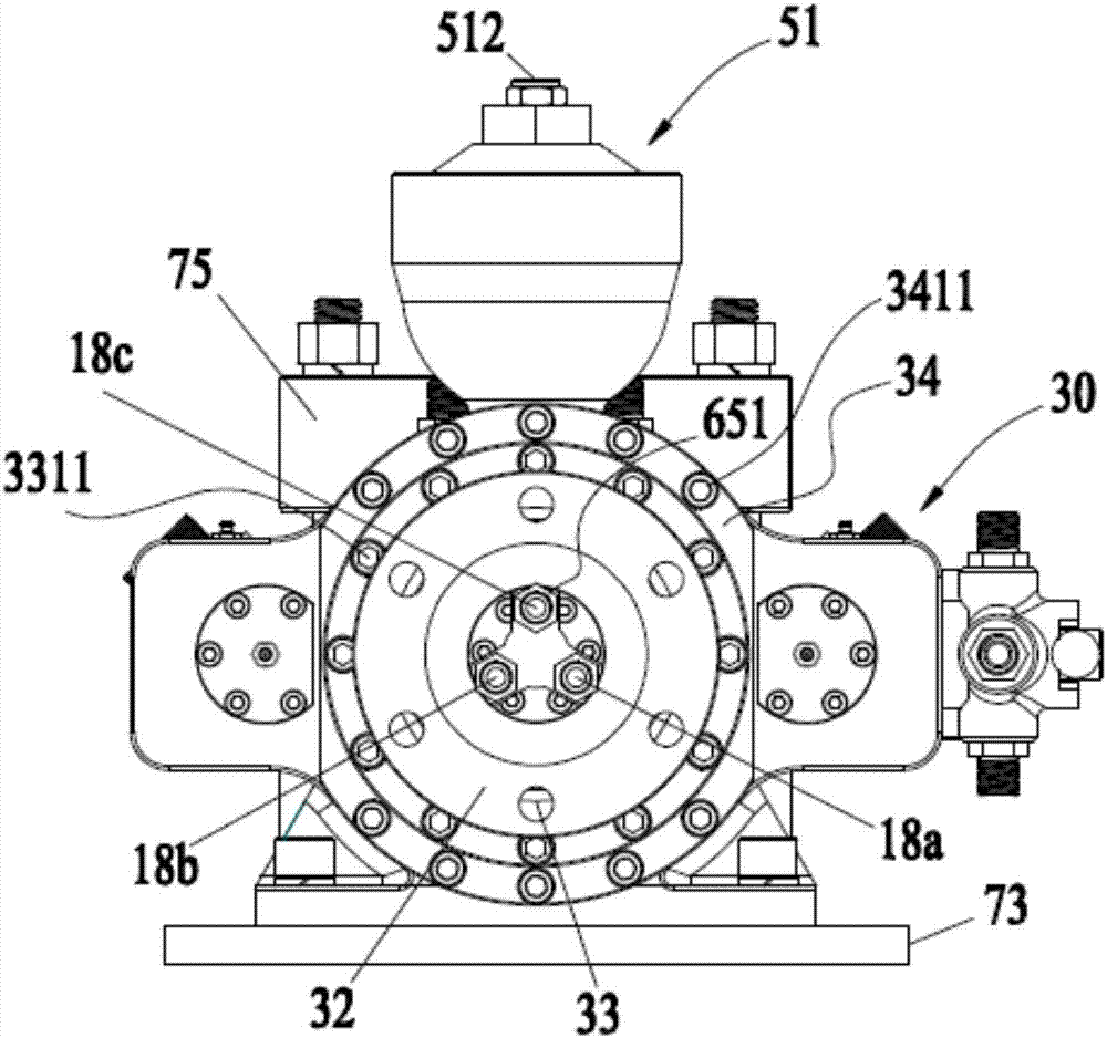
[0103] ginseng Figure 1 to Figure 15 Shown is a specific implementation of the high-pressure rotary jet power head of the present invention.

[0104] A high-pressure rotary spraying power head shown in this specific embodiment is mainly used for reinforcement of various soft and hard foundations, anti-seepage treatment of basements of high-rise buildings, regulation of large river dams, and reinforcement of railway and road bridge piers.

[0105] Specifically, in this embodiment, the high-pressure rotary spraying power head incl...


PUM


Abstract

The invention provides a high pressure jet grouting power head. The high pressure jet grouting power head comprises a front flange, an anti-hitting shell body, a shank, a rotary drilling mechanism, a vibration mechanism, a back flange, three diverters arranged in successive nests and an integrated slurry tube, which are arranged in sequence in the axial direction. The integrated structure slurry tube is formed by an injecting part with an integrated mechanism and a tube body. The front flange, the anti-hitting shell, the rotary drilling mechanism, the vibration mechanism and the diverters are penetrated by the tube body in sequence and in the longitudinal direction. Three independent transfer passages are formed within the tube body. Three axial spiral arrangements are formed on the side of the tube body and independently communicated with a diverter and a slurry feeding hole, an air feeding hole and a water feeding hole of the transfer passage. According to the high pressure jet grouting power head, independent transfer of three jet grouting medium of slurry, air and water is achieved; longitudinal length of the high pressure jet grouting power head is shortened; the height of the center of gravity of the high pressure jet grouting power head after installation is lowered; and the leakage of the jet grouting medium occurred at the jet grouting parts is prevented effectively.

Description

technical field [0001] The invention relates to the technical field of engineering excavation machinery, in particular to a high-pressure jet jet power head used in a jet jet drilling machine. Background technique [0002] The rotary jet drilling rig is a drilling tool used to transport slurry, compressed air and clean water, etc., and can ensure continuous dynamic and static tightness under high-pressure working conditions. In the rotary jet drilling rig, the drill pipe is one of the key components, which can transport the slurry and transport the slurry to the drill bit for ejection. [0003] A rotary jet drilling rig usually includes a mandrel through which the slurry is conveyed. Conventional mandrels typically have only one channel for the passage of the slurry and ejecting the slurry from the orifice. When spraying, the slurry is sprayed under the force provided by the rotary jet drilling machine, and at this time, the distance of the slurry spray is determined by th...

Claims


Application Information

Patent Timeline
Patent Type & Authority Applications(China)
IPC IPC(8): E21B7/18E21B17/18E02D5/46
CPCE21B7/18E21B17/18E02D5/46
Inventor 朱强
Owner 张家港保税区永大机械有限公司
Why Eureka
Try Eureka